
Self-demolding sealing and swelling water swelling mold of cup body

A self-release and water swelling technology, applied in the direction of pushing out equipment, etc., can solve the problems of core rod intubation wire drawing, easy cracking of the mold, and low service life of the mold, and achieve the effect of reducing wire drawing, shortening the length, and reducing mold cracking.

Pending Publication Date: 2021-11-02
浙江雄泰家居用品股份有限公司
View PDF10 Cites 0 Cited by
  • Summary
  • Abstract
  • Description
  • Claims
  • Application Information

AI Technical Summary

Problems solved by technology

[0003] Due to the deformation of the circular tube, it fits tightly into the cavity of the mold. Therefore, when the upper mold and the lower mold are separated, it will be affected by the friction force between the circular tube and the inner wall of the cavity, which makes it very difficult to separate the upper mold and the lower mold, resulting in mold jamming and difficulty in removal. Problems such as mold and low efficiency
[0004] At present, most of the water expansion molds use long mandrels, which have the functions of guiding, compressing, supporting, etc. However, during production, the insertion of the upper and lower mandrels is prone to wire drawing and even bruising.
[0005] The upper and lower mold cavities and the mold base of the water expansion mold are fixed by punching holes. After a period of use, the mold is easy to crack and the service life of the mold is not high

Method used


Image

  • Self-demolding sealing and swelling water swelling mold of cup body
  • Self-demolding sealing and swelling water swelling mold of cup body
  • Self-demolding sealing and swelling water swelling mold of cup body

Examples


Embodiment Construction

[0024] The following are specific embodiments of the present invention and in conjunction with the accompanying drawings, the technical solutions of the present invention are further described, but the present invention is not limited to these embodiments.

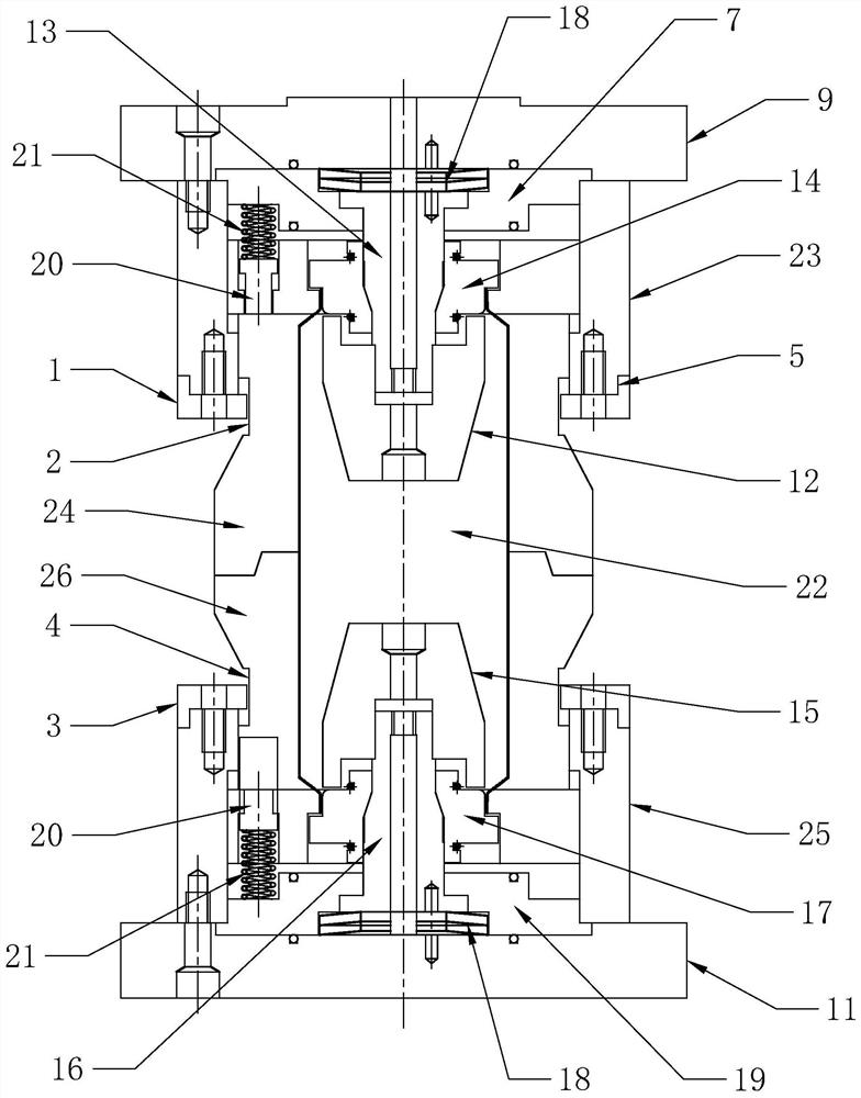
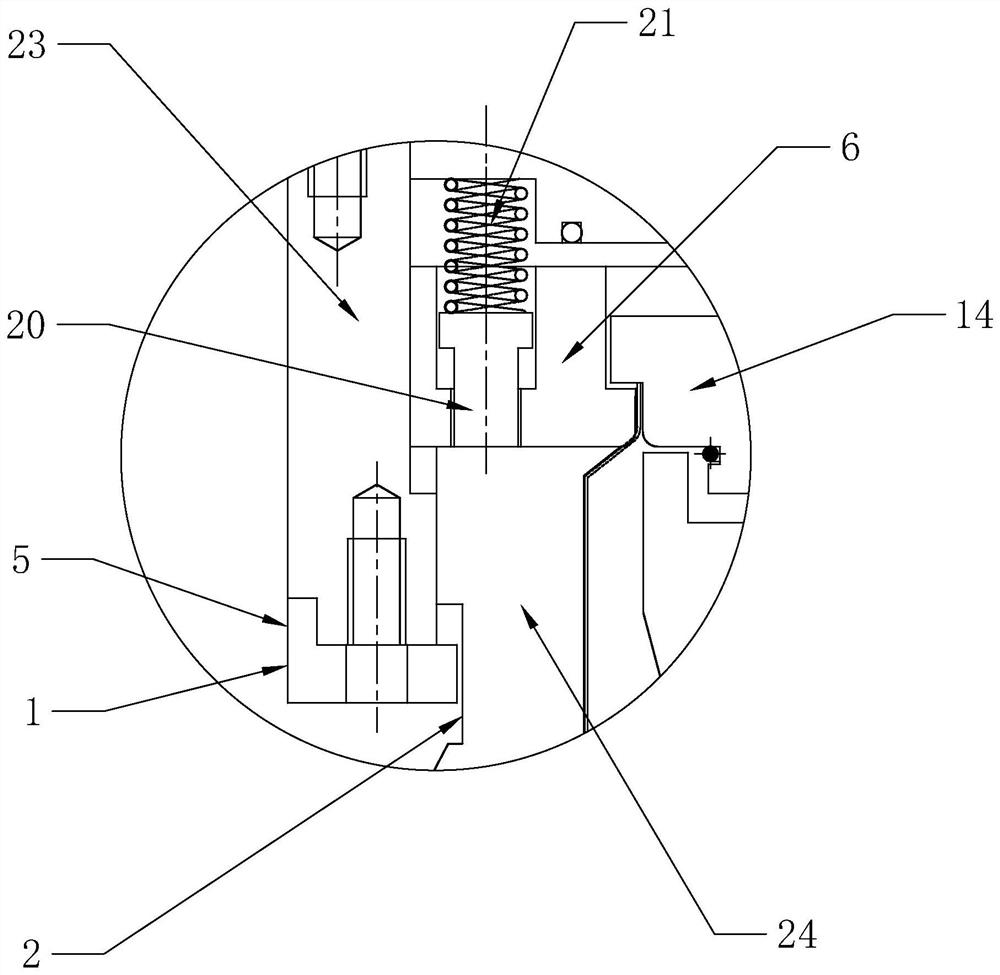
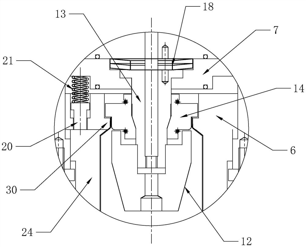
[0025] Such as figure 1 As shown, the self-demolding sealing and swelling mold of a cup body according to the present invention includes an upper mold assembly, a lower mold assembly arranged symmetrically up and down, and an upper mandrel movably arranged in the upper mold assembly Components, the lower core rod assembly that is movably arranged in the lower mold assembly, the water expansion molding space 22 is formed between the upper mold assembly, the lower mold assembly, the upper core rod assembly, and the lower core rod assembly, and the upper mold assembly includes Upper die cover 23, upper die cavity 24, lower mold assembly comprises lower die cover 25, lower die cavity 26, after described water expansion mold cl...


PUM


Abstract

The invention provides a self-demolding sealing and swelling water swelling mold of a cup body, and belongs to the technical field of forming equipment. The mold solves the problems that long core rods are adopted in existing water swelling molds, and wire drawing and even bumping are prone to being generated during long core rod pipe insertion. The mold comprises an upper mold assembly, a lower mold assembly, an upper core rod assembly and a lower core rod assembly, the upper mold assembly and the lower mold assembly are symmetrically arranged up and down, the upper core rod assembly and the lower core rod assembly are symmetrically arranged up and down, water swelling forming space is formed between the upper mold assembly and the lower mold assembly and between the upper core rod assembly and the lower core rod assembly, the upper mold assembly comprises an upper mold sleeve and an upper mold cavity, and the lower mold assembly comprises a lower mold sleeve and a lower mold cavity. After up-down mold compounding of the water swelling mold, the upper mold cavity can move upwards relative to the upper mold sleeve and is buckled with the upper core rod assembly to be used for blocking an upper opening of the water swelling forming space, and the lower mold cavity can move downwards relative to the lower mold sleeve and is buckled with the lower core rod assembly to be used for blocking a lower opening of the water swelling forming space. The mold has the advantages that the lengths of an upper core rod and a lower core rod are greatly reduced, and the situations of wire drawing, bumping and the like caused by pipe insertion during production are reduced.

Description

technical field [0001] The invention belongs to the technical field of molding equipment, and relates to a self-demolding sealing water swelling mold for a cup body. Background technique [0002] In the process of metal water cup processing, it is necessary to shape the cup body. The main process is to put the round tube into the forming mold first. The water swelling forming mold mainly includes an upper mold and a lower mold. Press to seal the product tightly. The forming mold seals and compresses the openings at both ends of the round tube, and then injects water from the inside of the round tube to deform the round tube from the inside to the outside to fit the mold cavity. After the water expansion process is completed, the upper mold needs to be Separate from the lower mold so that the formed round tube can be taken out. [0003] Due to the deformation of the circular tube, it fits tightly into the cavity of the mold. Therefore, when the upper mold and the lower mold ...

Claims


Application Information

Patent Timeline
IPC IPC(8): B21D26/047B21D45/04
CPCB21D26/047B21D45/04
Inventor 应泽民刘刚
Owner 浙江雄泰家居用品股份有限公司
Learn More