Strapping-free fixing axial tensioning clamp for fracture
A fixed shaft and tensioning technology, which is applied in the field of traction and fixation tools without binding flexible fixing parts, can solve the problems of affecting blood circulation, protruding sutured muscles, discomfort, etc., and achieve simplified operation procedures, reliable support, and good results Effect
- Summary
- Abstract
- Description
- Claims
- Application Information
AI Technical Summary
Problems solved by technology
Method used
Image
Examples
Embodiment 1
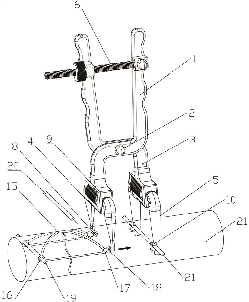
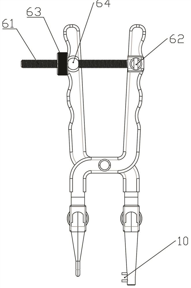
[0038] Embodiment 1: The flat-shaped tying-free fixing member can be applied and fixed on both sides of the fracture site. When it is tensioned and fixed, the distal and proximal ends of the fracture are tightened and fixed, which can significantly reduce the protrusion and improve the operation efficiency. Reduce the difficulty of surgery, improve blood circulation to facilitate the recovery of patients, improve the comfort of patients and other advantages. In order to fast fix the non-binding fastener, it is necessary to respectively provide the main collars at both ends of the non-binding fastener with axially outward pulling tension. Such as figure 1 As shown, the flat-shaped strap-free fixation member 15 includes a pair of front loops 16 at the front end and a pair of rear loops 17 at the rear end. Usually, when it is fixed, a hole is drilled at the distal end of the fracture and the front loop is placed. The ring 16 is set in the hole positions on both sides of the dril...
Embodiment 2
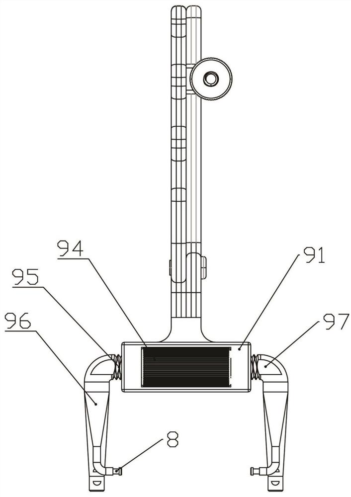
[0044] Embodiment 2: This embodiment provides a general-purpose pliers body, which is based on Embodiment 1, and the expansion and contraction is set between the left and right forks of the front tension fork 4 and / or the rear tension fork 5 Institution 9. That is: the front tension fork 4 and / or the rear tension fork 5 include two left and right forks that can slide relatively, and an expansion-contraction mechanism 9 is arranged between the two forks.
[0045] Such as figure 2 with Figure 10 As shown, the expansion-contraction mechanism 9 in this embodiment includes a rectangular housing 91, the middle part of the front and rear end surfaces of the housing 91 is transparent to form an inner cavity 92, and the left and right end walls of the inner cavity are respectively provided with non-circular end holes 93. A hand wheel 94 is set in the inner cavity 92 , the diameter of the first wheel is greater than the thickness between the front and rear end surfaces of the housin...
Embodiment 3
[0048] Embodiment 3: a kind of as Figure 4-Figure 6 The shown pliers body has the same main body structure as the pliers body in Embodiment 2, except that: (1) it is vertically fixed on the inner side of the two prongs of the rear tension fork 5 and faces the opposite columnar rod 14 . (2) Each fork of the front tension fork 4 and / or the rear tension fork 5 has a telescopic adjustment structure and a locking structure.
[0049] When the columnar rod 14 in other (1) is applied, it is necessary to directly insert the two columnar rods 14 at the lower end of the rear tension fork rod 5 into the drilled hole at the proximal end of the fracture after drilling the proximal end of the fracture, so that it is no longer used such as The support rod 21 in Embodiment 1. It can be seen that when this embodiment is applied, the expansion and contraction mechanism 9 as described in Embodiment 2 must be used. When in use, it is necessary to first adjust the rear tension fork rods 5 on bot...
PUM
 Abstract
Description
Claims
Application Information
 - R&D Engineer
- R&D Manager
- IP Professional
- Industry Leading Data Capabilities
- Powerful AI technology
- Patent DNA Extraction
Browse by: Latest US Patents, China's latest patents, Technical Efficacy Thesaurus, Application Domain, Technology Topic, Popular Technical Reports.
© 2024 PatSnap. All rights reserved.Legal|Privacy policy|Modern Slavery Act Transparency Statement|Sitemap|About US| Contact US: help@patsnap.com


