Device for evaluating corneal removal amount in refractive operation through optical coherence elastography

A technology of elastic imaging and refractive surgery, which is applied in medical science, ophthalmoscopes, and eye testing equipment, etc., can solve the problems of cornea injury and inability to stabilize the lens well, and achieve high safety and detection accurate results

Pending Publication Date: 2021-11-02
中山大学中山眼科中心南昌眼科医院
View PDF0 Cites 0 Cited by
  • Summary
  • Abstract
  • Description
  • Claims
  • Application Information

AI Technical Summary

Problems solved by technology

[0004] In order to overcome the shortcomings that the lens cannot be stabilized well when the corneal thickness of the patient is measured manually, and the cornea of ​​the patient may be damaged when the light is too strong, the technical problem of the present invention is to provide a lens that can fix the position of the lens and An optical coherence elastography device for evaluating corneal removal in refractive surgery that avoids too much light from damaging the patient's cornea

Method used


Image

  • Device for evaluating corneal removal amount in refractive operation through optical coherence elastography
  • Device for evaluating corneal removal amount in refractive operation through optical coherence elastography
  • Device for evaluating corneal removal amount in refractive operation through optical coherence elastography

Examples


Embodiment 1

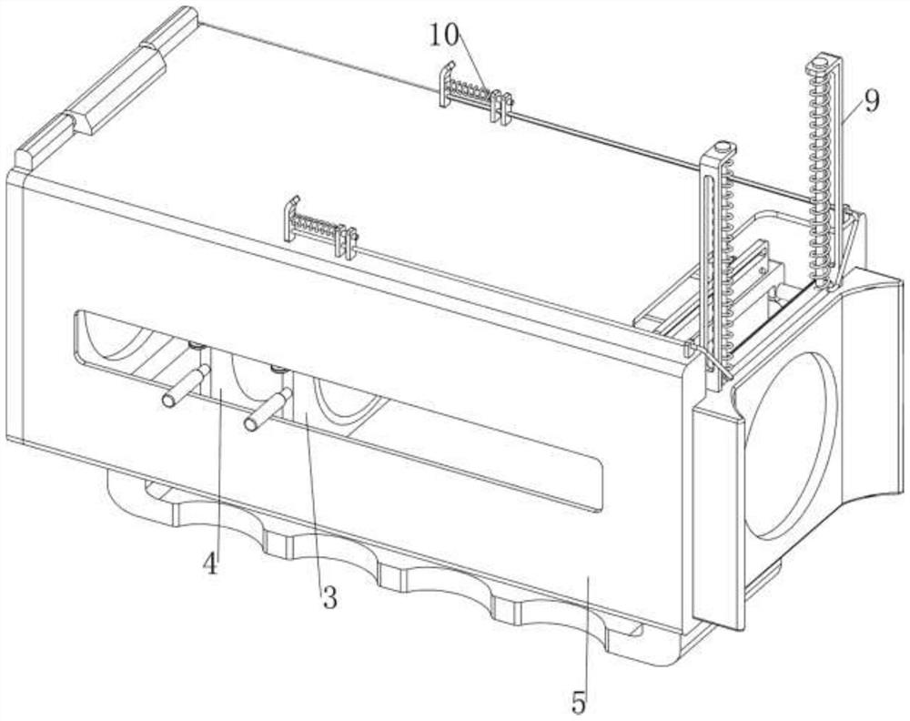
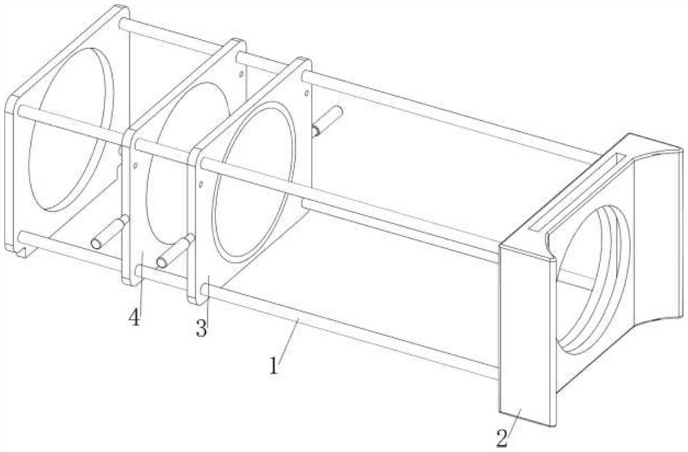
[0059] An optical coherence elastography device for evaluating corneal removal in refractive surgery, such as Figure 1-Figure 5 As shown, it includes a first support frame 1, a fixed frame 2, a concave mirror frame 3, a convex mirror frame 4, a shading mechanism 5 and a buffer mechanism 6, and the left side of the fixed frame 2 is provided with a first support frame 1, and on the first support frame 1 The sliding type is provided with a concave mirror frame 3, and the sliding type is provided with a convex mirror frame 4 on the first support frame 1. A buffer mechanism 6 is provided between them.

[0060] The shading mechanism 5 includes a frame body 50, a rotating plate 51 and a handle 52. The left side of the fixed frame 2 is provided with a frame body 50. The frame body 50 is located outside the first support frame 1. The upper part of the left side of the frame body 50 is rotatably provided with a rotating plate. 51. A handle 52 is provided at the bottom of the frame bod...

Embodiment 2

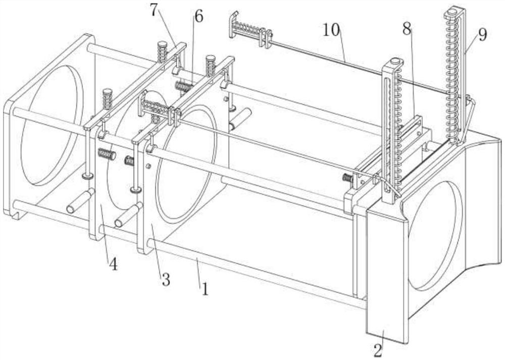
[0064] On the basis of Example 1, such as figure 2 , Figure 6 and Figure 7 As shown, a clamping mechanism 7 is also included, and the clamping mechanism 7 includes a first fixed column 70, a second spring 71, a first movable plate 72, a rubber ring 73, a second fixed column 74 and a fixed ring 75, and the concave mirror frame 3 and the top of the convex mirror frame 4 are all symmetrically provided with a first fixed column 70 front and back, and a first movable plate 72 is slidably provided between the first fixed columns 70 on the same side in the longitudinal direction, and the first fixed column 70 is wound with a first fixed column 70. Two springs 71, the two ends of the second spring 71 are respectively connected with the first fixed column 70 and the first movable plate 72, the left and right sides of the first movable plate 72 are all symmetrically provided with rubber rings 73, the rubber rings 73 are connected with the first support The frame 1 cooperates, and t...


PUM


Abstract

The invention relates to a corneal removal amount device, in particular to a device for evaluating the corneal removal amount in a refractive operation through optical coherence elastography. The technical problem of the invention is to provide the device for evaluating the corneal removal amount in the refractive operation through optical coherence elastography, which can fix the position of a lens and can prevent the cornea of a patient from being hurt by too strong light. The device for evaluating the corneal removal amount in the refractive operation through optical coherence elastography comprises a first supporting framearranged on one side of a fixing frame and the fixing frame, a concave mirror frame arranged on the first support frame in a sliding manner, and a convex mirror frame arranged on the first support frame in a sliding manner and arranged on one side of the concave mirror frame. Through cooperation of the concave mirror frame, the convex mirror frame, a shading mechanism and a buffer mechanism, the medical staff can detect the cornea thickness of a patient more conveniently, external light can be shielded, and the detection result is more accurate.

Description

technical field [0001] The invention relates to a corneal removal amount device, in particular to an optical coherence elastic imaging evaluation corneal removal amount device for refractive surgery. Background technique [0002] When light enters another medium with a different refractive index from one medium, the direction of travel will change, which is called refraction in ophthalmology. Medical staff can use the principle of refraction to perform a series of calculations on the patient's eyes. Corneal thickness is measured to facilitate follow-up corneal surgery for patients. [0003] Doctors generally measure the patient's corneal thickness through the cooperation of light and lens, use the light to pass through the lens and irradiate the patient's eyes, and then adjust the position of the lens to record the change of light to complete the measurement work. Such an operation process is relatively cumbersome. And when adjusting the position of the lens, the lens canno...

Claims


Application Information

Patent Timeline
Patent Type & Authority Applications(China)
IPC IPC(8): A61B3/10A61B3/12A61B3/00
CPCA61B3/1005A61B3/1208A61B3/1225A61B3/0075A61B3/0008
Inventor 黄国富赵雁之
Owner 中山大学中山眼科中心南昌眼科医院
Why Eureka
Try Eureka