Internal circulation breeding system
A culture system and recirculating culture technology, applied to the field of internal recirculating culture system, can solve the problems of low drainage, large drainage in aquaculture system, easy sinking of fecal particles, etc., and achieve the effect of reducing water discharge.
- Summary
- Abstract
- Description
- Claims
- Application Information
AI Technical Summary
Problems solved by technology
Method used
Image
Examples
Embodiment 1
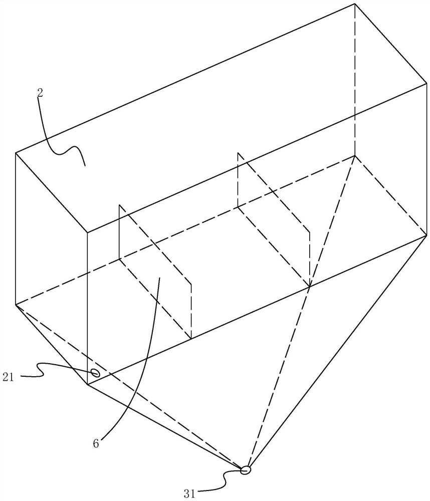
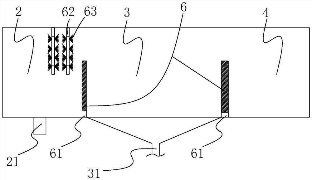
[0043] Such as image 3 As shown: the opening of the sewage discharge device is a sewage discharge pipe 31 arranged at the lower recess and communicated with the outside world, and the sewage discharge pipe 31 is provided with a switch mechanism. The switching mechanism here can be realized with a common cannula or a solenoid valve.
[0044] Such as Figure 5 , 6 , 7: when actually designing the position of the lower concave part, the position of the lower concave part can be located in the middle of the bottom surface of the sedimentation tank 3, or it can be located near the side of the bottom surface of the sedimentation tank 3, and it can also be directly located near the bottom surface near the included angle if necessary The place.
Embodiment 2
[0046] The sewage discharge device is a drainage pipe 32 extending from the top of the sedimentation tank 3 to the lower recess and having a water pump. The other end of the drainage pipe 32 extends to the outside. In addition, the principle of siphon can also be used to remove dirt. Here, the sewage is discharged through external pipelines. This design is more suitable for the transformation of existing culture ponds. That is, the sedimentation tank cannot be additionally provided with sewage pipelines 31. After redesigning the inverted cone or funnel shape for the bottom, the external pipelines can be introduced for sewage discharge. The drain pipe 32 here can be fixed on the bottom surface to ensure that its opening faces the lowest point of the inverted cone or funnel shape. This scheme can be processed on the basis of Example 1.
[0047] The water return device is a pneumatic water lifting device 41 . The pneumatic water lifting device 41 is used here mainly to save ele...
Embodiment 3
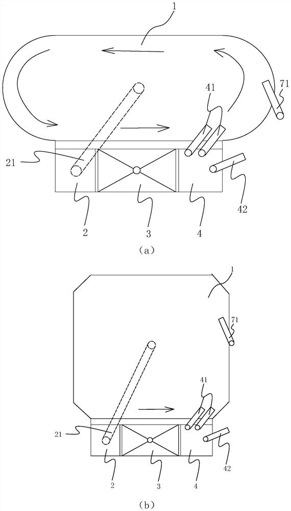
[0050] The culture pond 1 is round, oval or rectangular with cut corners. An intercepting rod 11 extending to the culture pond is provided on the edge of the culture pond 1; the intercepting rod 11 is flush with the liquid surface of the culture pond.
[0051]The main consideration here is that when returning water, the returning aquaculture water impacts the aquaculture water in the aquaculture pond, causing the aquaculture water in the aquaculture pond to form a vortex. flow. The floating object is intercepted by adding an intercepting rod, and then the floating object is gathered into the enclosed space by swinging the intercepting rod. Afterwards, the floating objects are removed by means of salvage, suction, etc.
PUM
 Abstract
Description
Claims
Application Information
 - R&D
- Intellectual Property
- Life Sciences
- Materials
- Tech Scout
- Unparalleled Data Quality
- Higher Quality Content
- 60% Fewer Hallucinations
Browse by: Latest US Patents, China's latest patents, Technical Efficacy Thesaurus, Application Domain, Technology Topic, Popular Technical Reports.
© 2025 PatSnap. All rights reserved.Legal|Privacy policy|Modern Slavery Act Transparency Statement|Sitemap|About US| Contact US: help@patsnap.com


