


Quick Research
Generate reliable direction feasibility study reports for your R&D in just a few steps.

Technical Q&A
Discover and master advanced knowledge NOW. Basics, ideas, possibilities, all at once.

Find Solutions
As an expert in R&D theories, this can generate solutions to your technical problems instantly.

Evaluate Feasibility
Analyze your overall solution with one click, know your potential R&D risks in advance.

Monitor Landscape
Get weekly tech updates, stay abreast of the latest tech innovations and key insights.
Reflection Ultrasonic Anemometer and Wind Velocity Detection Method
A wind speed detection and reflective technology, applied in speed/acceleration/shock measurement, fluid speed measurement, speed/acceleration/electric shock meter detailed information, etc., can solve excessive reflection of high wind speed signal, small echo signal amplitude, and signal attenuation and other problems, to achieve the effect of increasing the wind speed measurement range, large wind speed measurement range, and reducing wind speed error
- Summary
- Abstract
- Description
- Claims
- Application Information
AI Technical Summary
Problems solved by technology
Method used
Image


Examples
Embodiment 1
[0034] figure 1 The structure schematic diagram of the reflective ultrasonic anemometer of the embodiment of the present invention is given, as figure 1 As shown, the reflective ultrasonic anemometer includes:
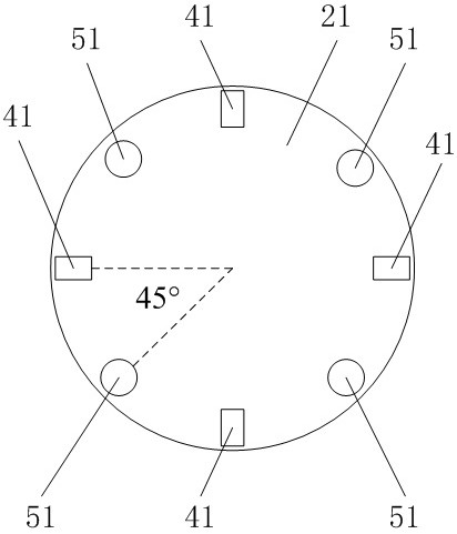
[0035] A base 21, a reflector 11 and an analysis unit, the reflector 11 is located on the upper side of the base 21 and has an upwardly convex concave reflective surface 31;
[0036] Transducers 41, four transducers 41 are arranged on the base 21;
[0037] Support columns 51, four support columns 51 are arranged on the base 21, and support the reflector 11; the support columns 51 are arranged between adjacent transducers 41;
[0038] Such as figure 2 As shown, the supporting columns 51 and the transducers 41 are alternately distributed, and on the base 21, the central angles corresponding to the adjacent supporting columns 51 and the transducers 41 are both 45°;
[0039] A calculation unit, the calculation unit is used to obtain the corrected wind speed according ...
Embodiment 2
[0045] An application example of the reflective ultrasonic anemometer and the wind speed detection method according to Embodiment 1 of the present invention.
[0046] In this application example, as Figure 1-2 As shown, in the reflective ultrasonic anemometer, four transducers 41 and four supporting columns 51 are arranged on the base 21, and supporting columns 51 are arranged between adjacent transducers 41, and the supporting columns 51 and the transducers The transducers 41 are arranged alternately, and the central angles corresponding to the adjacent supporting columns 51 and the transducers 41 are both 45°;
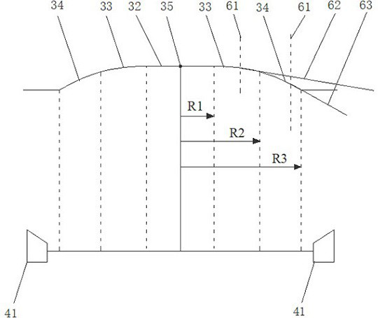
[0047] Such as image 3 As shown, the concave reflective surface 31 includes three circular reflective surfaces, the innermost circular reflective surface 32 is a plane, the radius R1=2.08mm, and the angle between the plane and the vertical direction is 90°;
[0048] The inner radius R2 of the outermost annular reflective surface 34 = 6.24mm, the outer radius R3 =...
Embodiment 3
[0061] According to the application example of the reflective ultrasonic anemometer and wind speed detection method of embodiment 1 of the present invention, the difference from embodiment 2 is:
[0062] The radius of the inner ring of the annular reflective surface 33 on the middle side is 2.08 mm, and the radius of the outer ring is 6.24 mm. The intersection line between the annular reflective surface 33 on the middle side and the vertical surface (including the center 35 of the concave reflective surface 31 ) is a straight line segment. The greater the distance from the center 35 of the concave reflection surface 31, the angle between the tangent line in the vertical plane and the vertical direction of each point (i.e. the reflection point) of the straight line segment remains unchanged, which is 88°;
[0063] The inner radius of the outermost annular reflective surface 34 is 6.24mm, the outer radius is 12.48mm, and the intersection line between the outermost annular reflect...
PUM
 Abstract
Description
Claims
Application Information
 - R&D Engineer
- R&D Manager
- IP Professional
- Industry Leading Data Capabilities
- Powerful AI technology
- Patent DNA Extraction
Browse by: Latest US Patents, China's latest patents, Technical Efficacy Thesaurus, Application Domain, Technology Topic, Popular Technical Reports.
© 2024 PatSnap. All rights reserved.Legal|Privacy policy|Modern Slavery Act Transparency Statement|Sitemap|About US| Contact US: help@patsnap.com