
Driving control method and device for dual-motor pure electric loader

A motor control, pure electric technology, applied in control devices, control drives, electric vehicles, etc., can solve the problems of heavy operation burden and short service life of brake pads, so as to improve the service life, save the energy consumption of the whole machine, and reduce the control burden effect

Active Publication Date: 2021-10-29
TIANJIN ENG MACHINERY INST
View PDF5 Cites 5 Cited by
  • Summary
  • Abstract
  • Description
  • Claims
  • Application Information

AI Technical Summary

Problems solved by technology

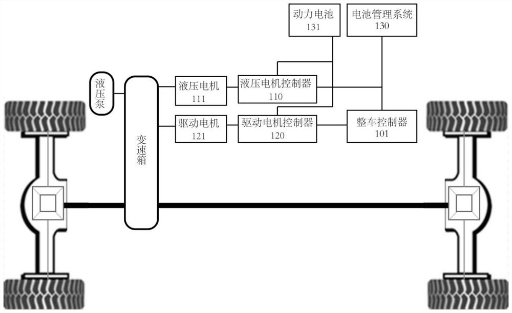
[0003] For dual-motor pure electric loaders, the hydraulic system and the walking system are completely independent, and are controlled independently by two electric motors. The control of the driving motor mostly refers to the control method of pure electric vehicles, in which the accelerator pedal corresponds to the target torque analysis method of the motor. , generally obtained by multiplying the value of the accelerator pedal by the maximum external characteristic curve of the motor. Although this method can produce strong power when shoveling and climbing, it is powerful on flat roads and has a full sense of pushing back, which is not suitable for driving a loader. Working conditions, the loader does not need to be very powerful on flat roads; in addition, the loader needs to undergo four front and rear direction changes for a typical V-shaped operation, and each time the direction change needs to step on the brakes to slow down, there is a heavy burden on the driver. , the service life of the brake pads is short, etc.

Method used


Image

  • Driving control method and device for dual-motor pure electric loader
  • Driving control method and device for dual-motor pure electric loader
  • Driving control method and device for dual-motor pure electric loader

Examples


Embodiment Construction

[0018] The present invention will be described in further detail below in conjunction with specific examples. It should be understood that the specific embodiments described here are only used to explain the present invention, not to limit the present invention.

[0019] In describing the present invention, it should be understood that the terms "center", "longitudinal", "transverse", "upper", "lower", "front", "rear", "left", "right", " The orientations or positional relationships indicated by "vertical", "horizontal", "top", "bottom", "inner" and "outer" are based on the orientations or positional relationships shown in the drawings, and are only for the convenience of describing the present invention and Simplified descriptions, rather than indicating or implying that the device or element referred to must have a particular orientation, be constructed and operate in a particular orientation, and thus should not be construed as limiting the invention.

[0020] In the descri...


PUM


Abstract

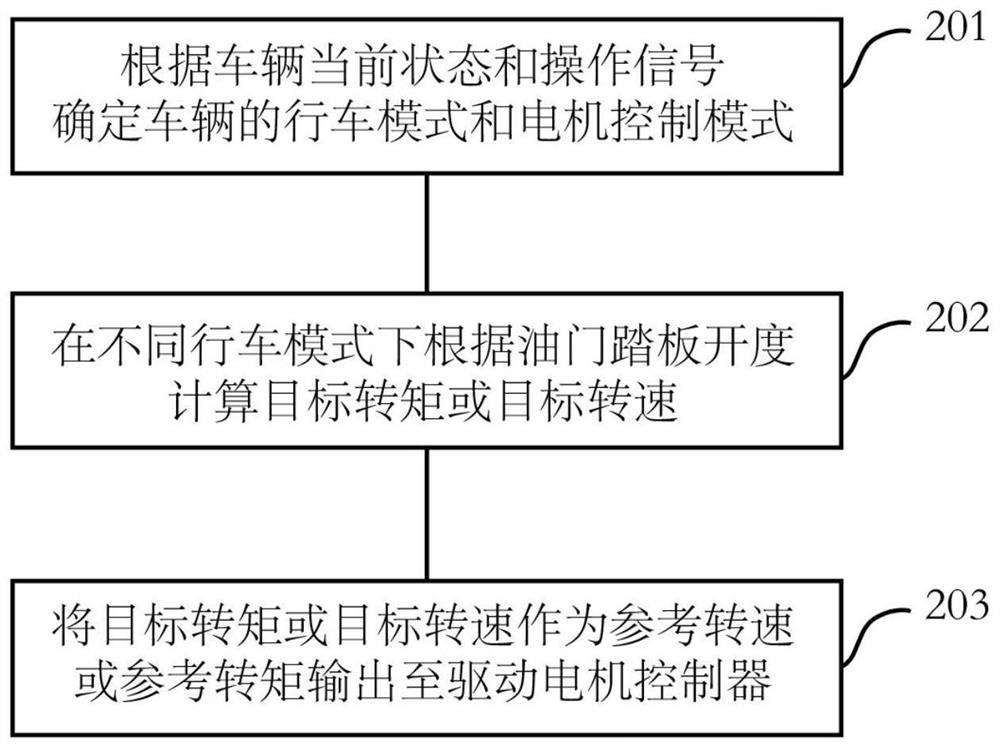
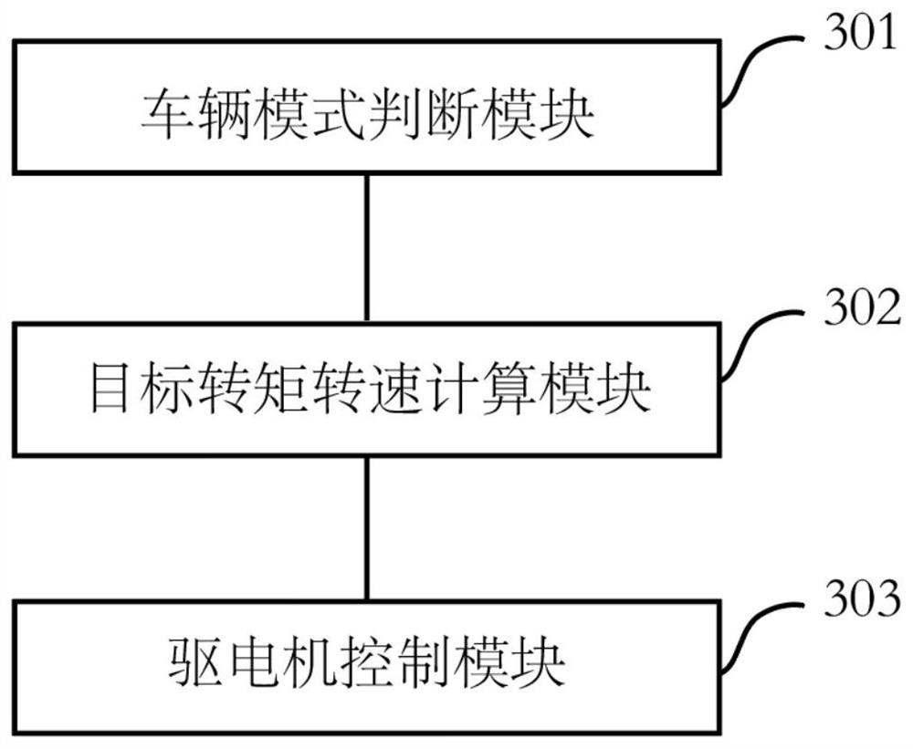
The invention discloses a driving control method and device for a dual-motor pure electric loader. The method comprises the steps of determining the driving mode and the motor control mode of a vehicle according to the current state and operation signals of the vehicle; calculating a target torque or a target rotating speed according to the opening degree of an accelerator pedal in different driving modes; and outputting the target torque or the target rotating speed as a reference rotating speed or a reference torque to a driving motor controller. A resistance self-recognition control method is introduced, and the limiting coefficient of the accelerator pedal is dynamically adjusted according to the difference value between the actual acceleration and the expected acceleration of the whole machine, so that the maximum value of the driving force sent by the loader on a flat road is limited, and the loader can output large driving force when running on a ramp or shoveling. In this way, it is guaranteed that the loader does not generate enough poke when running on the flat road, strong power is provided under the working conditions such as spading and the like needing large torque, and the requirements of a driver are met.

Description

technical field [0001] The invention relates to the technical field of construction machinery control, in particular to a driving control method and device for a dual-motor pure electric loader. Background technique [0002] As one of the most widely used earth-moving machinery in construction machinery products, wheel loaders are widely used in loading, unloading, pushing and construction of bulk materials such as soil, sand and gravel, and coal. [0003] For dual-motor pure electric loaders, the hydraulic system and the walking system are completely independent, and are controlled independently by two electric motors. The control of the driving motor mostly refers to the control method of pure electric vehicles, in which the accelerator pedal corresponds to the target torque analysis method of the motor. , generally obtained by multiplying the value of the accelerator pedal by the maximum external characteristic curve of the motor. Although this method can produce strong p...

Claims


Application Information

Patent Timeline
Patent Type & Authority Applications(China)
IPC IPC(8): B60L15/20
CPCB60L15/20B60L15/2018B60L2240/423B60L2240/421Y02T10/72
Inventor 李莺莺张卫东刘美艳马晓哲乔征贾启康段嘉慧
Owner TIANJIN ENG MACHINERY INST
Learn More