Temperature sensor and preparation method thereof

A technology of temperature sensor and horizontal direction, applied in the field of sensors, can solve problems such as inconvenient operation, fatigue failure, aging, etc., and achieve the effects of avoiding welding stress, prolonging service life and convenient operation

Pending Publication Date: 2021-10-26
NINGBO CRRC TIMES TRANSDUCER TECH CO LTD
View PDF6 Cites 0 Cited by
  • Summary
  • Abstract
  • Description
  • Claims
  • Application Information

AI Technical Summary

Problems solved by technology

[0005] First, the packaging of the base 100 and the probe assembly 200 is realized by filling glue. Since the base 100 is made of stainless steel, which has a different thermal expansion coefficient from the glue, and the temperature sensor is in a high-low temperature cycle environment for a long time, It is easy to cause "debonding" between the colloid and the base 100, resulting in a gap, and the surface of the probe assembly 200 corresponding to the glue filling part contains a rubber layer, so that the water vapor in the air enters the inside of the temperature sensor through the gap, causing aging. The rubber layer reduces the reliability of the temperature sensor;
[0006] Second, the base 100 and the probe assembly 200 are fixed by welding, resulting in welding stress at the weld between the probe assembly 200 and the base 100, and fatigue failure is prone to occur in a strong vibration environment;
[0007] Third, the connection between the probe assembly 200 and the adapter 300 is crimped, and the gap after crimping is filled with colloid, which is inconvenient to operate, and it is easy to pull out the cable 210 in the probe assembly 200
Although such a structural method solves the problem of water vapor entering after the colloid and the base 100 debond in the first method, aging the rubber layer on the surface of the probe assembly 200 , however, the cover plate 140 needs to be welded on the base 100 , so that only one slot hole for connecting the cover plate 140 is left on the base 100 instead of an open through hole, which makes it difficult to thread the probe assembly 200, and the welding and crimping in the first method bring The problem is also not well resolved

Method used


Image

  • Temperature sensor and preparation method thereof
  • Temperature sensor and preparation method thereof
  • Temperature sensor and preparation method thereof

Examples


Embodiment Construction

[0048] The following are specific embodiments of the present invention and in conjunction with the accompanying drawings, the technical solutions of the present invention are further described, but the present invention is not limited to these embodiments.

[0049]It should be noted that all directional indications (such as up, down, left, right, front, back...) in the embodiments of the present invention are only used to explain the relationship between the components in a certain posture (as shown in the figure). Relative positional relationship, movement conditions, etc., if the specific posture changes, the directional indication will also change accordingly.

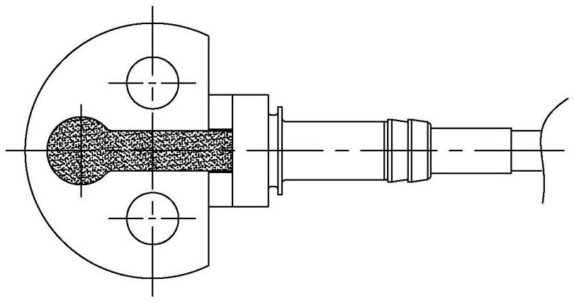
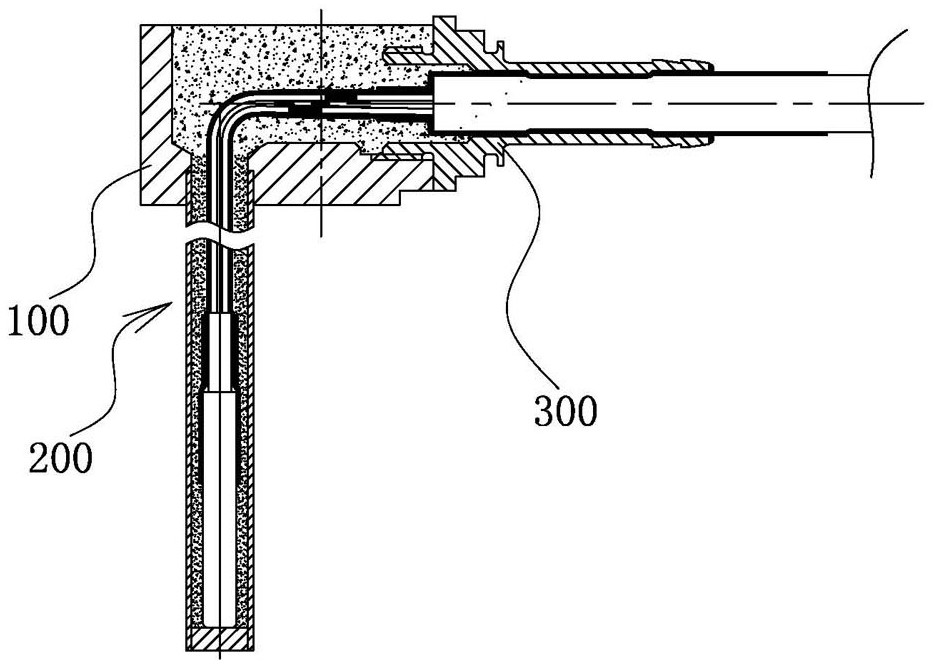
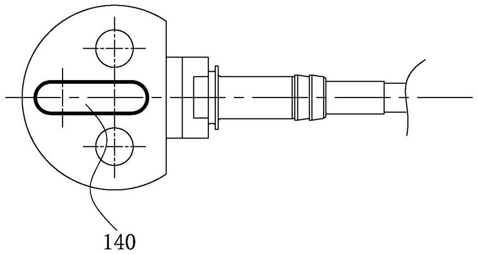
[0050] Such as Figure 5 to Figure 7 Shown, a kind of temperature sensor provided by the present invention comprises:

[0051] The base 100 is provided with a first passage 110 and a second passage 120 communicating with each other, and the first passage 110 is arranged in a vertical direction, and the second passa...


PUM


Abstract

The invention provides a temperature sensor and a preparation method and belongs to the technical field of sensors. The temperature sensor comprises a base, a probe assembly and a connecting pipe, wherein the base is provided with a first channel and a second channel, and a glue pouring port is formed at an intersection of the first channel and the second channel; the probe assembly comprises a cable, a metal sleeve which is nested and matched with the cable, and a sealing element which is sleeved outside the cable and is sleeved inside the metal sleeve; and the connecting pipe is nested on the probe assembly and is in threaded connection with the base to lock the probe assembly on the base. According to the temperature sensor provided by the invention, connection between the probe assembly and the base can be realized without welding, the relatively high sealing effect is achieved, and the service life of the temperature sensor is prolonged.

Description

technical field [0001] The invention belongs to the technical field of sensors, and relates to a temperature sensor, in particular to a temperature sensor and a preparation method. Background technique [0002] Temperature sensors are installed in traction motors, gearboxes, and axle boxes of various rolling stock in rail transit, and convert the temperature of the measured object into electrical signals, which are provided to the on-board system in real time, which is an important part of the safe operation of rolling stock. At present, the temperature sensors used in the market generally adopt the following two methods: [0003] Method 1, such as figure 1 and figure 2 As shown, the temperature sensor includes a base 100, a probe assembly 200 installed on the base 100, and a joint 300 nested on the probe assembly 200, wherein the base 100 is sealed by potting glue, and the The connection between the base 100 and the probe assembly 200 is fixed by welding, the connection...

Claims


Application Information

Patent Timeline
Patent Type & Authority Applications(China)
IPC IPC(8): G01K13/00G01K1/14G01K1/00
CPCG01K13/00G01K1/14G01K1/00
Inventor 张燕亮刘丹顾忠辉
Owner NINGBO CRRC TIMES TRANSDUCER TECH CO LTD
Why Eureka
Try Eureka