Pneumatic tire

A technology of pneumatic tires and tires, applied in tire parts, tire treads/tread patterns, vehicle parts, etc., can solve problems such as decreased production efficiency, and achieve the effect of improving followability and improving recycling.

Pending Publication Date: 2021-10-22
SUMITOMO RUBBER IND LTD
View PDF6 Cites 0 Cited by
  • Summary
  • Abstract
  • Description
  • Claims
  • Application Information

AI Technical Summary

Problems solved by technology

Therefore, when manufacturing a tire, there is a problem that a process of winding a reinforcing cord on the outer peripheral surface of the tire frame member is required, and the production efficiency is reduced.

Method used


Image

  • Pneumatic tire
  • Pneumatic tire
  • Pneumatic tire

Examples


Embodiment

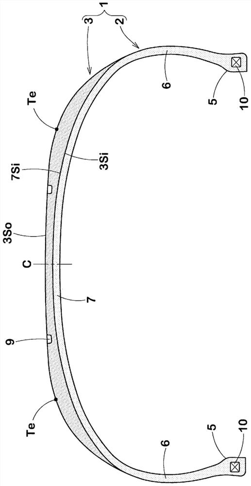
[0081] In order to confirm the effect of the present invention, according to the specifications of Table 1, a figure 1 Passenger car tires (195 / 65R15) of the construction shown.

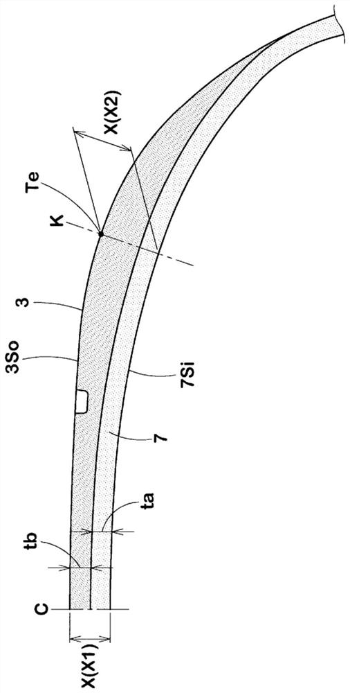
[0082] In the comparative example and the embodiment, only the resin material used in the tire frame member 2, the resin material used in the tread ground contact member 3, and the tread thickness ratio X2 / X1 are different. In addition, the ratio X2 / X1 is adjusted by varying the thickness tb of the tread contact member 3 .

[0083] For the comparative example and the embodiment, by computer simulation, calculate the ground contact area of ​​the tire when it is perpendicular to the road surface under the conditions of normal rim (15×6JJ), normal internal pressure (230kPa) and normal load (3.43kN), and compare them with each other .

[0084]

[0085] is an index of grip, and is represented by an index of 10 in Comparative Example 1. The larger the value, the larger the ground contact area and the ...


PUM

PropertyMeasurementUnit
modulusaaaaaaaaaa

Abstract

The present invention improves recyclability, as well as ensuring grip by suppressing a reduction in ground contact area even when a tread reinforcement element has been eliminated. The present invention comprises a tire frame member 2 including a bead portion 5, a sidewall portion 6, and an under-tread portion 7, and a tread ground contact element 3 provided on an outer side of the under-tread portion 7. The tire frame member 2 and the tread ground contact element 3 are constituted by a resin material, and a tensile modulus Ea of the tread ground contact element 3 is lower than a tensile modulus Eb of the tire frame member 2. A tread thickness X2 at a tread ground contact edge Te is greater than 1.2 times and less than 5.0 times a tread thickness X1 at a tire equator C.

Description

technical field [0001] The present invention relates to a pneumatic tire in which a tire frame member is formed of a resin material. Background technique [0002] In conventional pneumatic tires, the basic characteristics of the tire can be secured by using cord materials such as vulcanized rubber and organic fibers or steel fibers. However, vulcanized rubber has a problem that material recycling is difficult. In addition, the use of cord materials, particularly carcass cords, complicates the manufacturing process and increases manufacturing costs. [0003] Therefore, in Patent Document 1 below, a carcassless tire is proposed in which a tire frame member is formed of a resin material. The tire frame member includes a pair of bead portions, a pair of sidewall portions extending from the pair of bead portions, and a crown portion connecting the pair of sidewall portions. In addition, a tread made of vulcanized rubber is disposed on the crown portion. [0004] Patent Docume...

Claims


Application Information

Patent Timeline
Patent Type & Authority Applications(China)
IPC IPC(8): B60C11/00B60C5/01
CPCB60C11/00B60C5/01B60C2011/0033B60C11/01B60C1/0016B60C1/0041B60C11/0008B60C2009/0276B60C2011/0025
Inventor 安藤宽太
Owner SUMITOMO RUBBER IND LTD
Why Eureka
Try Eureka