High-voltage switchgear network architecture

A network architecture and high-voltage switch technology, applied in the direction of ring electromagnetic network, data exchange network, electromagnetic network arrangement, etc., can solve problems such as time and energy consumption, loose wiring, economic loss, etc.

Pending Publication Date: 2021-10-22
ELECTRIC POWER RES INST OF GUANGXI POWER GRID CO LTD +1
View PDF2 Cites 0 Cited by
  • Summary
  • Abstract
  • Description
  • Claims
  • Application Information

AI Technical Summary

Problems solved by technology

The number of cables in these signal loops can reach as many as hundreds of cores in one interval, and tens of thousands of cores in a substation. The work of how to connect these cables is important and complicated, which consumes a lot of design units, manufacturing units, construction and commissioning units. time and energy
Due to the difference in interlocking and other requirements, the current cable circuit lacks standardization. Different manufacturers, different projects and different intervals of the same project have different wiring, which seriously affects the efficiency of engineering design, equipment manufacturing, on-site installation and commissioning, and later operation and maintenance.
[0003] At present, the laying, connection and debugging of open switch cables need to be carried out at the construction site of the substation, which makes it difficult to control the workload and quality of this part. Some substations even have operating accidents caused by cable wiring errors after several years of operation.
A large number of cables have risks such as electromagnetic compatibility, loose wiring, long-term oxidation and aging of cable connectors, resulting in poor contact or leakage grounding during operation.
When the cable fault is serious, it may cause the switch to refuse to move during the accident, threatening the safe and stable operation of the power grid, and will also cause great economic losses

Method used


Image

  • High-voltage switchgear network architecture
  • High-voltage switchgear network architecture
  • High-voltage switchgear network architecture

Examples


Embodiment 1

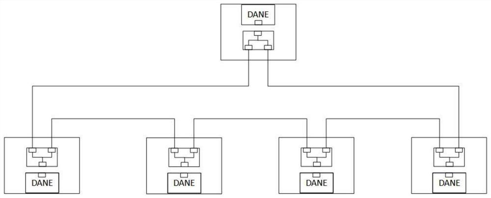
[0026] like figure 1 Shown is a schematic diagram of a high-voltage switchgear network architecture. The grid architecture adopts an optical fiber ring network topology, including several dual-connected device nodes, each node is a DANE (Double Attached Nodewith EAN Protocol), and each device The node is equipped with two Ethernet access ports A and B connected to the optical fiber ring network, and operates in full-duplex mode so that both ports can send and receive data frame messages, and each device node can automatically Adaptable, plug and play. When a device node on the ring network is used as a sending node to send data on the ring network, the sending device node sends data frame messages with the same core content in both forward and reverse directions on the ring network. When a transmission device node on the ring network When a line failure occurs, the receiving device node on the ring network can still receive the data frame message transmitted by the path in th...


PUM


Abstract

The invention provides a high-voltage switchgear network architecture, which uses an optical fiber ring network topological structure, equipment nodes on the network architecture access an optical fiber ring network through two access ports carried by the equipment nodes, and data can be simultaneously sent to or received from the ring network clockwise and anticlockwise through the two access ports. When any one of the equipment nodes has a fault, receiving and transmitting of data are not affected, and the effect of communication zero-delay recovery is achieved. Meanwhile, each equipment node is provided with a unique ID number, a mapping relation between an equipment ID and an equipment node source MAC address of the , a mapping relation between the equipment ID and a publishing and subscribing multicast address and a mapping relation between the device equipment ID and the IP address are established, the equipment ID nodes transmit real-time commands and states through a goose protocol, transmit real-time sampling data through an SV protocol, and carry out software maintenance and upgrading, operation information uploading and the like through a TCP/IP protocol. The plug-and-play and configuration-free effects of each equipment node on the ring network are realized.

Description

technical field [0001] The invention relates to the field of substation equipment control network, in particular to a high-voltage switchgear network architecture. Background technique [0002] In the current domestic smart substations, the intelligence of switches is mainly reflected in the application of smart components such as smart terminals. By installing on-site intelligent components in the control cabinet next to the switch, the signal transmitted by the traditional cable is converted into an optical fiber signal to interact with secondary equipment such as protection, measurement and control, and the cables and cables between the control cabinet and the control and protection equipment are eliminated. related questions. At the same time, a large number of cables are still used as the carrier of signal transmission between the primary switchgear body and the central control cabinet. Interlocking and other circuits. The number of cables in these signal loops can r...

Claims


Application Information

Patent Timeline
Patent Type & Authority Applications(China)
IPC IPC(8): H04L12/437H04L12/24H04B10/275H04B10/035H02J13/00
CPCH04L12/437H04L41/0809H04B10/275H04B10/035H02J13/00017H02J13/00036
Inventor 王晓明林翔宇李文伟宋益苏毅芦宇峰彭博雅
Owner ELECTRIC POWER RES INST OF GUANGXI POWER GRID CO LTD
Why Eureka
Try Eureka