Gate lifting and water controlling system for hydropower station

A hydropower station and gate control technology, applied in electrical components, circuit devices, emergency power supply arrangements, etc., can solve the problems of uneven personnel skill levels, inability to make accurate judgments, misjudgments, etc., to achieve convenient operation and improve economy. Operational efficiency, the effect of reducing workload

Inactive Publication Date: 2021-10-22
MINGXING ELECTRIC SICHUAN
View PDF3 Cites 0 Cited by
  • Summary
  • Abstract
  • Description
  • Claims
  • Application Information

AI Technical Summary

Problems solved by technology

[0003] At the same time, in some hydropower stations, especially small hydropower stations, the relationship between the lifting height of the floodgate and the water level and flow of the forebay is mostly judged by the on-site experience of the personnel, and it is impossible to make an accurate judgment; In this situation, misoperation and misjudgment are prone to occur.

Method used


Image

  • Gate lifting and water controlling system for hydropower station

Examples


example 1

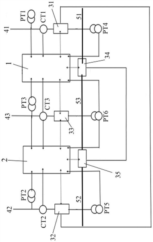
[0094] This example will combine figure 1 To describe an operation mode of the power control module of the water control system of the hydropower station, the operation mode is a backup input mode of the incoming line.

[0095] Among them, the plant power system is mainly supplied by the third power supply incoming line 43; the first generator power supply incoming line 41 and the second generator power supply incoming line 42 are used for backup, and the first standby automatic switching device 1 and the second standby automatic switching device 2 evenly charged. The start-up time limits of the first standby automatic switch-on device 1 and the second standby automatic switch-on device 2 are set and coordinated, and the delays of the first and second standby automatic switch-on devices and the standby power supply are 3 seconds and 10 seconds respectively.

[0096] Before a fault occurs, whether the initial state of each switch is: the first switch 31 and the second switch 3...

example 2

[0101] This example will combine figure 1 To describe another operation mode of the water control system of the hydropower station gate lift, this mode is segmental backup.

[0102] Among them, the factory power system is independently powered by the first generator power supply line 41, the second generator power supply line 42 and the third power supply line 43, and the third power supply line 43 is a 35kV power supply line; the first , The second backup self-injection device is charged. The start-up time limits of the first standby automatic switch-on device 1 and the second standby automatic switch-on device 2 are set and coordinated, and the delays of the first and second standby automatic switch-on devices and the standby power supply are 3 seconds and 10 seconds respectively.

[0103] Before a fault occurs, whether the initial state of each switch is: the first switch 31 , the second switch 32 and the third switch 33 are all closed, and the fourth switch 34 and the fif...


PUM


Abstract

The invention provides a gate lifting and water controlling system for a hydropower station, wherein the hydropower station is provided with a first power source, a second power source and a third power source, the first power source and the second power source are standby power sources, the third power source is a frequently-used power source. The system comprises a liquid level monitoring module, a gate monitoring module, a control module and a power source regulation and control module, wherein the liquid level monitoring module comprises a liquid level meter, the control module is connected with the liquid level monitoring module and can control a gate to ascend and descend, the gate monitoring module can collect the data of the gate and transmit the data to the control module, and the power source regulation and control module is also connected with the first power source, the second power source and the third power source, can switch among the three power sources, is also connected with the gate and supplies power to the gate. According to the invention, safe and economical operation of the hydropower station can be guaranteed, the gate opening degree can be accurately controlled according to the forebay water level, and the labor intensity and workload of personnel are relieved; and the electric interruption time can be shortened from minute level to second level, so that the equipment operation is safer and more reliable.

Description

technical field [0001] The invention relates to the field of electricity control and adjustment, in particular to a water control system for lifting gates of a hydropower station. Background technique [0002] The control of the flood gate of the hydropower station is very important, especially at the critical moment of water storage and flood discharge. If the power supply system of the hydropower station collapses due to a fault and the factory power disappears, and the backup power supply cannot be switched in time, it will easily lead to very serious consequences. However, the existing backup power supply of some hydropower stations cannot be switched automatically, and it is completed by the on-duty personnel, such as manually starting the diesel generator. However, there are fewer on-duty personnel, and there may be older problems, which will make the power switch in an emergency untimely and take a long time to operate. Therefore, how to achieve timely switching bet...

Claims


Application Information

Patent Timeline
Patent Type & Authority Applications(China)
IPC IPC(8): H02J9/06H02J9/08H02J11/00
CPCH02J9/06H02J9/08H02J11/00Y02B10/70
Inventor 黄炜刘伟王贤福唐治华林放晏靖杰陈劲风任飞何兴国贺先国王扬周宏海
Owner MINGXING ELECTRIC SICHUAN
Why Eureka
Try Eureka