
Laser fixing device and fixing method for c-mount laser welding line

A fixed device, laser technology, applied in the direction of lasers, laser parts, semiconductor lasers, etc., can solve the problems of large deviation of laser welding line position, difficult to guarantee consistency, affecting product quality, etc., to achieve simple structure, convenient and reliable operation. , the effect of low cost

Active Publication Date: 2022-06-07
Shandong Huaguang Optoelectronics Co. Ltd.
View PDF8 Cites 0 Cited by
  • Summary
  • Abstract
  • Description
  • Claims
  • Application Information

AI Technical Summary

Problems solved by technology

The laser fixing technology often used for C-mount laser welding wires is to clamp the fixing hole of the C-mount laser heat sink block with tweezers with one hand, and gently place the laser on the copper plate in the middle of the feeder of the wire bonding machine, and then feed The pressure plate on the device moves down to fix the laser, and the other hand adjusts the position of the laser by manipulating the control handle of the device. Press the button on the control handle, and the P knife of the wire welding machine moves down to weld the gold wire to the COS and the upper end of the electrode. , complete the wire bonding work of the laser. After the wire bonding is completed, lift the pressure plate, and use tweezers to remove the laser from the copper plate to complete the wire bonding work. This fixing method is used for C-mount laser wire bonding. The method is simple but the operation is more troublesome. , only one laser welding line can be carried out at a time, and it is difficult to operate without long-term professional training
During the laser welding process, the operator will inevitably touch other structures of the laser, which is very easy to cause product pollution caused by human factors
Moreover, due to the poor fixation of the laser on the wire bonding machine, the vibration generated during the wire bonding process will easily cause the laser to move, resulting in a large deviation in the position of the laser welding wire, resulting in poor welding accuracy and difficult to guarantee consistency
At the same time, due to the very thin thickness of the electrode and the soft material, it is inevitable that the electrode will be bent during the wire welding process, which will affect the quality of the product.

Method used


Image

  • Laser fixing device and fixing method for c-mount laser welding line
  • Laser fixing device and fixing method for c-mount laser welding line
  • Laser fixing device and fixing method for c-mount laser welding line

Examples


Embodiment 1

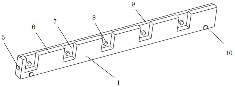
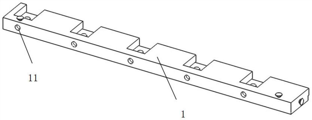
[0042] like Figure 1-Figure 9 As shown, this embodiment provides a laser fixing device for a C-mount laser welding wire, including a fixing bar 1, a pressing sheet 2, and a retaining bar 3; There are fixing pins I5, N evenly arranged retention grooves 7 are arranged in the middle of the fixing bar 1, a fixing column 8 is arranged in the middle of each fixing slot 7, and a platform 6 is arranged on one side of each fixing slot 7, The upper end of the fixing strip 1 is provided with a concave edge 9, the two sides of the front end of the fixing strip 1 are respectively provided with fixing pins II 10, and the lower end of the fixing strip 1 is provided with N evenly arranged circular holes 11; A raised edge 16 is provided, N evenly arranged gaps 13 are arranged in the middle of the pressing sheet 2, and N evenly arranged protrusions 17 are arranged on one side of the gap 13 at the lower end of the pressing sheet 2, and one side of each protrusion 17 is respectively provided wit...

Embodiment 2

[0052] Utilize the method for fixing the C-mount laser with the laser fixing device of the C-mount laser welding wire provided in Example 1, and the specific steps are as follows:

[0053] (1) Take out the laser fixing device, push the side edge 12 of the tablet 2 upwards, move the tablet 2 to the uppermost end of the device, push the bar 3 down, move the bar 3 to the lowermost end of the device, and expose the fixing groove to the greatest extent 7. It is convenient to place the heat sink block 22;

[0054] (2) Clamp the heat sink block 22 of the C-mount laser 18 with tweezers, align the fixing hole 23 of the heat sink block 22 with the fixing post 8 on the fixing bar 1, and place the heat sink block 22 in the fixing slot 7;

[0055] (3) After the heat sink blocks 22 are placed in all the fixing grooves 7, gently push the bar 3 upward to move the bar 3 to the uppermost end, and press the pressing piece 2 downward, and the pressing piece 2 passes through the guide groove I14 t...


PUM


Abstract

The invention relates to a laser fixing device and a fixing method for a C-mount laser welding line. The laser fixing device includes a fixing bar, a pressing piece and a retaining bar; There is a gap in the middle of the pressing sheet, which corresponds to the fixing groove, and the sides of the pressing sheet are provided with symmetrically structured sides, through which the pressing sheet is connected to the fixing bar; The laser fixing device used in the C-mount laser welding line of the present invention has the advantages of simple structure, low cost and convenient and reliable operation. The device of the present invention is small in volume, simple in structure and convenient in maintenance and repair. The device fixes 5 C-mount lasers at a time, and can realize the continuous welding line work of C-mount lasers. Compared with the previous single laser fixing welding line, the production efficiency of laser welding line is improved. ten times.

Description

technical field [0001] The invention relates to a laser fixing device and a fixing method for a C-mount laser welding wire, belonging to the technical field of semiconductor laser packaging. Background technique [0002] After decades of development, semiconductor lasers are more and more well known to the society and have been applied in many fields. The photoelectric conversion efficiency of semiconductor lasers is over 60%, which is much higher than that of other similar products. Lasers have the advantages of high efficiency, long life, high beam quality, good stability and compact structure, and are widely used in optical fiber communication, laser pumping, medical equipment, night vision lighting, laser printers and other fields. With the increasing development and maturity of semiconductor technology, laser diodes have greatly improved in terms of power, conversion efficiency, wavelength extension, and operating life. [0003] In recent years, the demand for high-pow...

Claims


Application Information

Patent Timeline
Patent Type & Authority Patents(China)
IPC IPC(8): H01S5/0237H01S5/02345H01S5/024H01S5/026
CPCH01S5/026H01S5/02469
Inventor 张广明刘琦李沛旭
Owner Shandong Huaguang Optoelectronics Co. Ltd.
Learn More