
A kind of micro-coaxial transmission line based on 3D printing and its manufacturing method

A coaxial transmission line and 3D printing technology, applied in the field of 3D printing, can solve the problem of unsuitable processing accuracy for millimeter-level or sub-millimeter-level coaxial structures, large-scale structures, long cycle times for batch processing, and complicated manufacturing processes for micro-coaxial structures. problems, to achieve the effect of easy mass production, light weight and heavy weight

Active Publication Date: 2022-06-07
CHINA ELECTRONIC TECH GRP CORP NO 38 RES INST
View PDF6 Cites 0 Cited by
  • Summary
  • Abstract
  • Description
  • Claims
  • Application Information

AI Technical Summary

Problems solved by technology

CN202010430174.7 patent document adopts metal 3D printing method to make internal and external conductors. The metal 3D printing method is a one-dimensional printing method. The cycle of scale structure and batch processing is long and the cost is high, and the processing accuracy is not suitable for millimeter-level or submillimeter-level coaxial Fabrication of the structure
The CN202010039385.8 patent document is based on silicon-based micro-molds made by semiconductor technology, and uses micro-electroforming technology to make micro-coaxial structures. Although this method has high processing accuracy and can reach micron levels, the silicon mold manufacturing process is complicated and disposable. , leading to complex fabrication process and high cost of micro-coaxial structure

Method used


Image

  • A kind of micro-coaxial transmission line based on 3D printing and its manufacturing method
  • A kind of micro-coaxial transmission line based on 3D printing and its manufacturing method
  • A kind of micro-coaxial transmission line based on 3D printing and its manufacturing method

Examples


Embodiment Construction

[0034] In order to make the purposes, technical solutions and advantages of the embodiments of the present invention clearer, the technical solutions in the embodiments of the present invention will be clearly and completely described below in conjunction with the embodiments of the present invention. Obviously, the described embodiments are part of the present invention. examples, but not all examples. Based on the embodiments of the present invention, all other embodiments obtained by those of ordinary skill in the art without creative efforts shall fall within the protection scope of the present invention.

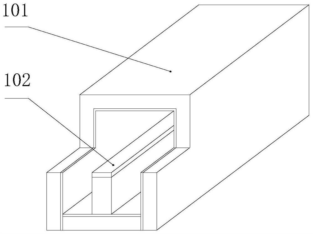
[0035] The micro-coaxial transmission line based on 3D printing proposed by the present invention is such as figure 1 As shown, a transmission line intermediate body 101 and a transmission line end 102 are included.

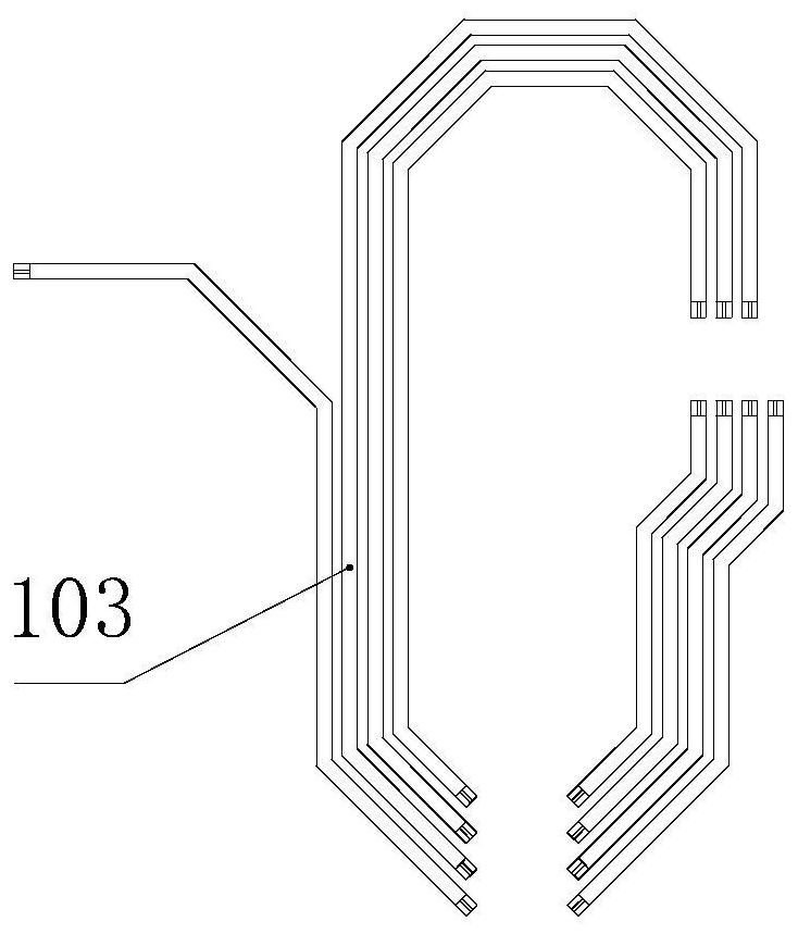
[0036] In this embodiment, the micro-coaxial transmission line based on 3D printing is in the form of a straight line. Of course, the micro-coaxial trans...


PUM


Abstract

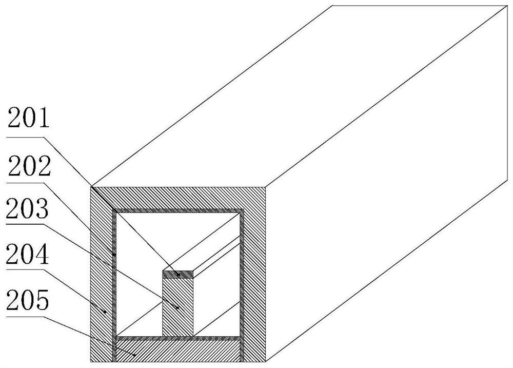
The invention provides a micro-coaxial transmission line based on 3D printing and a manufacturing method thereof, wherein the transmission line intermediate body (101) includes an inner conductor (201), an outer conductor (202), a support structure (203), and an outer frame cap (204 ) and the outer frame bottom plate (205), the materials of the support structure (203), the outer frame cap (204) and the outer frame bottom plate (205) are all photocurable resins; the inner surface of the outer frame bottom plate (205) is covered with an outer conductor ( 202); the support structure (203) is located above the center of the outer frame bottom plate (205), and its upper surface is covered with an inner conductor (201); the outer frame cap (204) is buckled upside down on the outer frame bottom plate (205); the transmission line end The part (102) is located at the end of the transmission line intermediate body (101), and is hollowed out relative to the top of the transmission line intermediate body (101). The micro-coaxial transmission line proposed by the present invention takes light-curing 3D printing as the core. Compared with the production of the current micro-coaxial structure, it has the advantages of convenient batch production, short production cycle, and high processing accuracy.

Description

technical field [0001] The invention belongs to the field of 3D printing, and specifically relates to a micro-coaxial transmission line based on 3D printing technology and a manufacturing method thereof. Background technique [0002] The transmission of microwave signals in RF electronic systems is the key. At present, the interconnection between chips mostly adopts horizontal or vertical transmission structures such as microstrip lines, striplines, coplanar waveguides, and vertical through holes. In recent years, the demand for high-frequency applications has become prominent. With the rapid development of microwave integrated circuit technology, radio frequency systems have evolved towards miniaturization and high density. When the system integration or frequency is very high, traditional interconnection and transmission technology exposes many drawbacks, such as large insertion loss and inter-line coupling. High integration, high performance application requirements. Th...

Claims


Application Information

Patent Timeline
Patent Type & Authority Patents(China)
IPC IPC(8): H01P3/06H01P11/00
CPCH01P3/06H01P11/005
Inventor 盛文军陈兴玉周金文于坤鹏
Owner CHINA ELECTRONIC TECH GRP CORP NO 38 RES INST
Learn More