A two-dimensional high-speed scanning mirror device

A technology of high-speed scanning and mirrors, which is applied in the direction of instruments, optics, and radio wave measurement systems, etc., can solve problems such as thermal deformation of mirrors, and achieve the effects of reduced loss, low volume, weight and power consumption, and easy adjustment

Active Publication Date: 2022-02-01
北京瑞控信科技股份有限公司
View PDF0 Cites 0 Cited by
  • Summary
  • Abstract
  • Description
  • Claims
  • Application Information

AI Technical Summary

Problems solved by technology

[0007] The purpose of the present invention is to provide a two-dimensional high-speed scanning mirror device for solving at least one of the above technical problems, which can achieve a larger range of rotation angles, and at the same time avoid cable dragging and coil heating in the moving coil design The thermal deformation of the reflector caused by thermal deformation and other technical problems, and the structure is reasonable, compact and easy to install

Method used


Image

  • A two-dimensional high-speed scanning mirror device
  • A two-dimensional high-speed scanning mirror device
  • A two-dimensional high-speed scanning mirror device

Examples


Embodiment Construction

[0060] In order to make the purpose, technical solutions and advantages of the embodiments of the present invention clearer, the technical solutions in the embodiments of the present invention will be clearly and completely described below in conjunction with the drawings in the embodiments of the present invention. Obviously, the described embodiments It is a part of embodiments of the present invention, but not all embodiments. The components of the embodiments of the invention generally described and illustrated in the figures herein can be arranged and designed in a variety of different configurations.

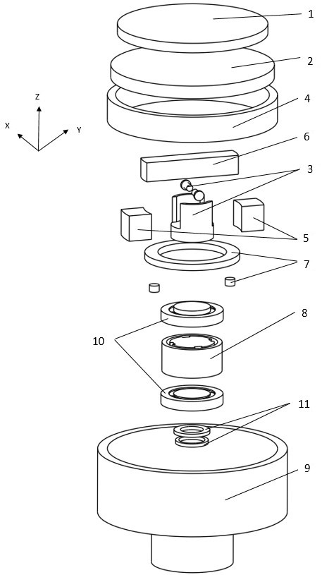
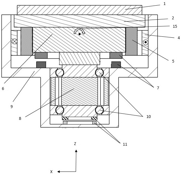
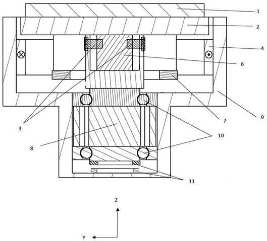
[0061] Please refer to Figure 1 to Figure 6 , The embodiment of the present invention provides a two-dimensional high-speed scanning mirror device, which includes a mirror 1 , a mirror bracket 2 , a voice coil motor, a rotating motor 8 , a rotating bearing assembly 10 and a housing 9 .

[0062] The reflector 1 is fixed on the front end of the housing 9 through the reflec...


PUM


Abstract

The invention discloses a two-dimensional high-speed scanning mirror device, which includes a mirror, a mirror bracket, a voice coil motor, a rotating motor, a rotating bearing assembly and a casing; the mirror is fixed on the The front end of the housing; the rotating motor is fixed at the rear end of the housing through the rotating bearing assembly; the voice coil motor is fixed between the mirror bracket and the rotating motor. The two-dimensional high-speed scanning mirror device of the present invention can achieve a larger range of rotation angles, and at the same time avoid technical problems such as cable dragging in the moving coil design, thermal deformation of the mirror caused by coil heating, and the structure is reasonable and compact , easy to install.

Description

technical field [0001] The invention relates to the technical field of photoelectric scanning and tracking, in particular to a two-dimensional high-speed scanning mirror device. Background technique [0002] The fast reflector is a component that works between the light source or receiver and the target to adjust and stabilize the visual axis of the optical system or the beam pointing. By using a voice coil motor to precisely control the deflection direction of the reflector, the beam deflection angle can be precisely controlled. It is used to realize the rapid adjustment of the "deflection-tilt" azimuth angle of the mirror, and can be used in applications such as line-of-sight stabilization or scan compensation in the optoelectronic field. Due to its advantages of compact structure, fast response, high working bandwidth, and high pointing accuracy, it is widely used in the applications of lidar and lidar systems, mainly including 3D mapping, aircraft landing, spacecraft doc...

Claims


Application Information

Patent Timeline
Patent Type & Authority Patents(China)
IPC IPC(8): G02B26/10
CPCG01S7/4817
Inventor 孔凡辉肖立亮
Owner 北京瑞控信科技股份有限公司
Why Eureka
Try Eureka