A metal door and window lock hole grinding device

A technology for metal doors, windows and keyholes, applied in metal processing equipment, grinding machines, grinding machine parts, etc., can solve the problems of inconvenience and poor adaptability, and achieve the effect of convenient use, small size, and avoiding excessive grinding.

Active Publication Date: 2021-11-30
南通铂莱德节能科技有限公司
View PDF7 Cites 0 Cited by
  • Summary
  • Abstract
  • Description
  • Claims
  • Application Information

AI Technical Summary

Problems solved by technology

[0004] Aiming at the deficiencies of the prior art, the present invention provides a metal door and window lock hole grinding device, which solves the problem that the inner wall of the lock hole usually needs to be polished after the lock hole on the metal door and window is processed, so as to avoid the burrs on the inner wall from affecting the fit of the connectors. , but the currently used grinding device is poor in adaptability. When encountering a keyhole with a different aperture, it is necessary to replace the corresponding grinding block, which is inconvenient to use.

Method used


Image

  • A metal door and window lock hole grinding device
  • A metal door and window lock hole grinding device
  • A metal door and window lock hole grinding device

Examples


Embodiment 1

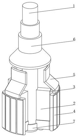
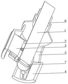
[0034] see Figure 1-4 , the present invention provides a technical solution: a metal door and window lock hole grinding device, specifically comprising:

[0035] A fixed column 1, one side of the fixed column 1 is fixedly connected with a fixed frame 2, the inner wall of the fixed frame 2 is slidably connected with a telescopic plate 3, and one side of the telescopic plate 3 extends to the outside of the fixed frame 2 and is fixedly connected with an arc-shaped grinding device 4;

[0036] Extrusion plate 5, this extrusion plate 5 is arranged on the top of arc grinding device 4, and extrusion plate 5 is provided with vertical and inclined two sections;

[0037] Squeeze the shrink tube 6, the squeeze shrink tube 6 is sleeved on the fixed column 1 and screwed with the fixed column 1, the shape of the squeezed shrink tube 6 matches the shape of the squeeze plate 5;

[0038] A control device 7, the control device 7 is arranged at the bottom of the fixed column 1 and fixedly conne...

Embodiment 2

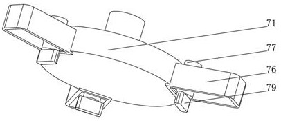
[0044] see Figure 1-5 On the basis of Embodiment 1, the present invention provides a technical solution: the arc-shaped grinding device 4 includes an arc-shaped mounting plate 41, and both ends of the arc-shaped mounting plate 41 are fixedly connected with an arc-shaped hinge plate 42, and the arc-shaped hinge plate 42 There are multiple groups and damping pads are provided at the joints between the two. The outer side of the arc-shaped installation plate 41 is provided with an installation groove 43. The inner wall of the installation groove 43 is provided with an arc-shaped grinding plate 44. One side of the arc-shaped installation plate 41 is connected to the telescopic The plate 3 is fixedly connected, and the inner wall of the installation groove 43 is connected with the side of the arc-shaped grinding plate 44 through the groove block.

[0045] An arc-shaped grinding device 4 is provided, and the inside of the arc-shaped grinding device 4 is provided with an arc-shaped ...


PUM


Abstract

The invention relates to the technical field of metal processing, and discloses a metal door and window lock hole grinding device, which specifically includes: a fixed column, one end side of the fixed column is fixedly connected with a fixed frame, the inner wall of the fixed frame is slidably connected with a telescopic plate, and the telescopic plate One side extends to the outside of the fixed frame and is fixedly connected with an arc-shaped grinding device; an extruding plate, which is arranged on the top of the arc-shaped grinding device, and the extruding plate is provided with two vertical and inclined sections; extruding and shrinking The extrusion shrinkage sleeve is set on the fixed column and is threadedly connected with the fixed column. The shape of the extrusion shrinkage tube is adapted to the shape of the extruded plate; the control device is arranged at the bottom of the fixed column and It is fixedly connected with a fixed column, and the invention relates to the technical field of metal processing. The metal door and window lockhole grinding device is convenient to adapt to lockholes of different diameters, does not need to replace the grinding head, is convenient to use, and can be replaced with a drill bit, does not need special driving equipment, is small in size, and is easy to carry and use.

Description

technical field [0001] The invention relates to the technical field of metal processing, in particular to a metal door and window lock hole grinding device. Background technique [0002] Metal processing, referred to as metalworking, refers to the production activities that humans process metal elements or materials with metal characteristics mainly composed of metal elements. It is a process technology that processes metal materials into articles, parts, and components, including large parts such as bridges and ships, and even small components of engines, jewelry, and watches. It is widely used in science, industry, artwork, Handicrafts and other different fields. The lockholes on metal doors and windows usually need to be polished on the inner wall of the lockhole after the machining is completed, so as to avoid the burrs on the inner wall from affecting the fit of the connectors. However, the currently used grinding device has poor adaptability. It is inconvenient to re...

Claims


Application Information

Patent Timeline
Patent Type & Authority Patents(China)
IPC IPC(8): B24B5/48B24B9/04B24B41/04B24B27/00
CPCB24B5/48B24B9/04B24B41/04B24B27/0092
Inventor 沈凯凯
Owner 南通铂莱德节能科技有限公司
Why Eureka
Try Eureka