Sealing structure of stirring shaft of reaction kettle

A technology of sealing structure and reactor, which is applied to the sealing of engines, engine components, chemical/physical/physicochemical processes, etc., and can solve the problem of damage between devices inside the sealing structure, increased wear of the internal components of the sealing structure, and reduced service life, etc. Problems, achieve the effect of strengthening protection and improving service life

Inactive Publication Date: 2021-10-22
无锡广和盛化工设备有限公司
View PDF0 Cites 0 Cited by
  • Summary
  • Abstract
  • Description
  • Claims
  • Application Information

AI Technical Summary

Problems solved by technology

[0002] With the development of society, the stirring device of the reactor is widely used in the present society, and it is involved in many aspects such as petroleum, chemical industry, food, medical treatment, etc., but the stirring shaft and the coupling in the traditional reactor are closely matched , the rotation of the stirring blade is driven by the force of the key, and the material easily enters the inside of the connector through the gap of the shaft hole, causing bacterial contamination. Therefore, it is necessary to add a sealing structure on the surface of the stirring shaft of the reactor to realize the sealing of the connection between the stirring shaft and the reactor. leakage
[0003] At present, the sealing structure of the stirring shaft of the reactor still adopts the traditional mechanical seal structure. In actual use, because the sealing structure of the special reaction environment of the reactor is often in a high temperature environment, the mechanical seal device is expanded by high temperature, resulting in the inside of the sealing structure The gap between the components is reduced, the wear is increased during high-speed rotation, and the service life is reduced. In the special reaction environment of the reactor, the contact between the sealing structure and the reaction liquid is easy to occur. Most of the reactions are corrosive to a certain extent, and the sealing structure is easy to corrode. Causes damage to the internal device of the sealed structure, and there are certain defects

Method used


Image

  • Sealing structure of stirring shaft of reaction kettle
  • Sealing structure of stirring shaft of reaction kettle
  • Sealing structure of stirring shaft of reaction kettle

Examples


Embodiment Construction

[0021] The following will clearly and completely describe the technical solutions in the embodiments of the present invention with reference to the accompanying drawings in the embodiments of the present invention. Obviously, the described embodiments are only some, not all, embodiments of the present invention. Based on the embodiments of the present invention, all other embodiments obtained by persons of ordinary skill in the art without making creative efforts belong to the protection scope of the present invention.

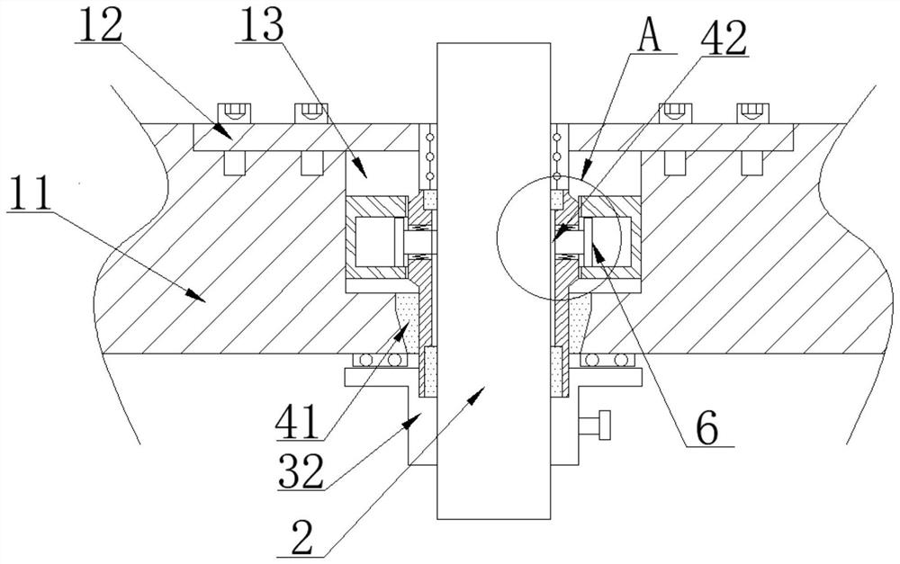
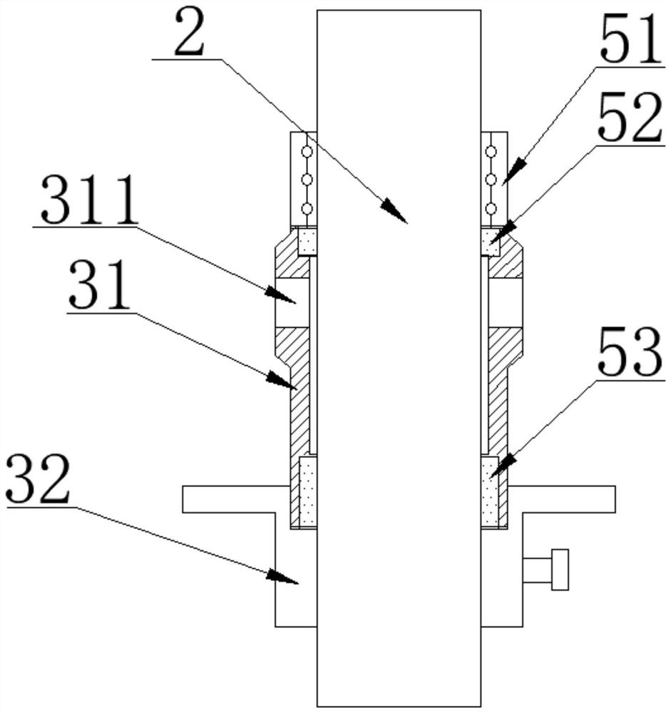
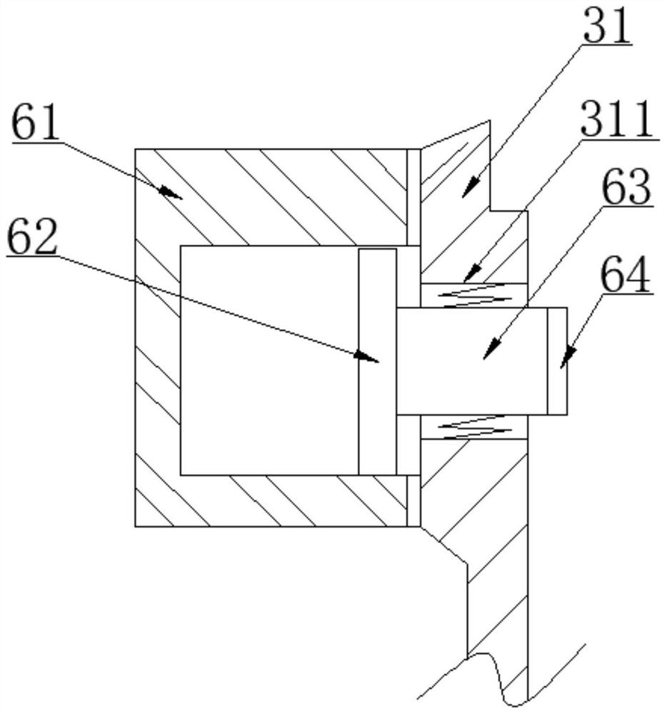
[0022] as attached Figure 1-4 The sealing structure of a stirring shaft of a reactor shown includes a reactor body 1, a rotating shaft 2 and a rotating support part 5. The reactor body 1 includes a connecting end 11 of a rotating shaft, a connecting end cover 12, a connecting end 11 of a rotating shaft, and a connecting end The cover 12 is fixedly connected by a screw, and the surface of the rotating shaft 2 is sleeved with an anti-corrosion protection mechan...


PUM


Abstract

The invention discloses a sealing structure of a stirring shaft of a reaction kettle, and particularly relates to the field of reaction kettles. The structure comprises a reaction kettle body, a rotating shaft and a rotating support part, the surface of the rotating shaft is sleeved with an anti-corrosion protection mechanism. The anti-corrosion protection mechanism comprises an anti-corrosion supporting lantern ring and an anti-corrosion flange cover. Anti-swelling protection mechanisms are arranged on the two sides of the anti-corrosion supporting lantern ring; the anti-swelling protection mechanism comprises anti-swelling top glue and an anti-swelling gap, and the anti-swelling gap is located on the inner side of the anti-corrosion supporting lantern ring. An oil seal mounting sliding cavity is formed in the inner side of the rotating shaft connecting end, and an oil pressure supporting part is slidably mounted on the inner side of the oil seal mounting sliding cavity. By arranging the anti-expansion protection mechanism and the oil pressure supporting part, the anti-expansion protection mechanism abuts against the rotating shaft, and when the shaft seal component is heated to expand, the influence of expansion can be eliminated by abutting against the anti-expansion top rubber and the anti-expansion gap; meanwhile, the oil pressure supporting part can continuously support and protect the rotating shaft through the top supporting rod after the shaft seal part is heated and expanded, so that the rotating shaft is kept stable.

Description

technical field [0001] The invention relates to the technical field of reactors, and more specifically, the invention relates to a sealing structure for a stirring shaft of a reactor. Background technique [0002] With the development of society, the stirring device of the reactor is widely used in the present society, and it is involved in many aspects such as petroleum, chemical industry, food, medical treatment, etc., but the stirring shaft and the coupling in the traditional reactor are closely matched , the rotation of the stirring blade is driven by the force of the key, and the material easily enters the inside of the connector through the gap of the shaft hole, causing bacterial contamination. Therefore, it is necessary to add a sealing structure on the surface of the stirring shaft of the reactor to realize the sealing of the connection between the stirring shaft and the reactor. leakage. [0003] At present, the sealing structure of the stirring shaft of the react...

Claims


Application Information

Patent Timeline
Patent Type & Authority Applications(China)
IPC IPC(8): B01J19/00F16J15/16
CPCB01J19/0073F16J15/166
Inventor 许和清
Owner 无锡广和盛化工设备有限公司
Why Eureka
Try Eureka