
Ion current separation structure and spray type disinfection device using it

A technology of separation structure and disinfection device, which is applied in the field of ion separation, can solve the problems of low efficiency of negative ion separation, low safety in use, and limitations in application fields, and achieve the effects of ensuring disinfection coverage, low production cost, and high working precision

Active Publication Date: 2022-01-14
雷神等离子科技(杭州)有限公司
View PDF4 Cites 0 Cited by
  • Summary
  • Abstract
  • Description
  • Claims
  • Application Information

AI Technical Summary

Problems solved by technology

[0008] Aiming at the above technical problems of low anion separation efficiency, low safety in use, complex structure, high production cost and limited application field, the present invention provides an ion flow separation structure and a spray-type disinfection device using it, which adopts a low-voltage direct current power supply Generate electric field to separate positive and negative ions, simple structure, high ion separation efficiency, energy saving and environmental protection, high safety in use, low production cost, and can be practically applied to the scene of disinfecting new coronaviruses, which can improve the efficiency of disinfection and sterilization, and ensure Disinfection coverage of spray-type disinfection device

Method used

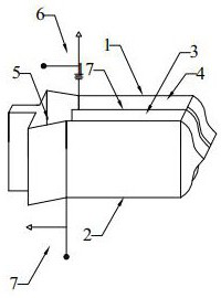
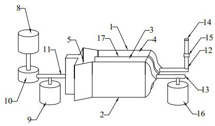
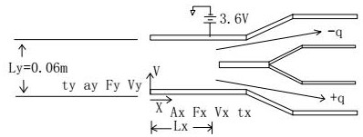

Image

  • Ion current separation structure and spray type disinfection device using it
  • Ion current separation structure and spray type disinfection device using it
  • Ion current separation structure and spray type disinfection device using it

Examples


Embodiment 1

[0033] Such as figure 1 Shown is an ion flow separation structure of the present invention and a spray-type disinfection device using it. The ion current separation structure includes: a positive separator 1, which is connected to a positive terminal 6, and the positive terminal 6 is connected to a low-voltage DC power supply. The voltage range of the low-voltage DC power supply is greater than or equal to 3.6V and less than or equal to 12V. In this embodiment, preferably 3.6V, more economical and safe. Of course, for small ion separation devices, the lower voltage limit of the low-voltage power supply used in the application of the ion current separation structure is not limited; the negative separator 2 is connected to the negative terminal 7, and the negative terminal 7 is provided with a grounding wire. A separator 17 is provided between the positive electrode separator 1 and the negative electrode separator 2 . One end of the positive electrode separator 1 and one end o...


PUM

PropertyMeasurementUnit
electric potential / voltageaaaaaaaaaa
thicknessaaaaaaaaaa
lengthaaaaaaaaaa

Abstract

The invention discloses an ion flow separation structure and a spray-type disinfection device using the same. The ion flow separation structure includes: a positive electrode separator connected with a positive end connected with a low-voltage DC power supply; a negative electrode separator connected with a negative electrode There is a grounding wire at the negative end; there is a separator between the positive separator and the negative separator; one end of the positive separator and one end of the negative separator together form a trumpet-shaped inlet; between the positive separator and the separator A positive ion channel is formed; an anion channel is formed between the negative electrode separator and the separator plate; one end of the positive ion channel and the negative ion channel is connected to the trumpet-shaped inlet and the other end is respectively a positive ion outlet and an anion outlet. The invention has the following beneficial effects: (1) the structure is simple, stable and reliable, and the use safety is high; (2) the cost is low; (3) the efficiency of separating positive and negative ions is high; (3) the disinfection efficiency is high and the disinfection coverage is better.

Description

technical field [0001] The invention relates to the technical field of ion separation, in particular to an ion flow separation structure and a spray type disinfection device using the ion flow separation structure. Background technique [0002] The charged particles formed after atoms or atomic groups lose or gain electrons are called ions, and negative ions refer to ions with one or more negative charges, also known as "anions". Some molecules can also form ions under special circumstances. For example, the ionic state of oxygen is generally an anion, also called negative oxygen ion. [0003] Negative ions can kill bacteria. The main principle of negative ion sterilization and air purification is that after the combination of negative ions and bacteria, the bacteria will undergo structural changes or energy transfers, resulting in the death of the bacteria, which will eventually sink to the ground and rapidly reduce the bacteria in the air. At the same time, negative ions ...

Claims


Application Information

Patent Timeline
Patent Type & Authority Patents(China)
IPC IPC(8): A61L9/14A61L9/22A61L2/14A61L2/22F24F6/00F24F8/10F24F8/30F24F13/28
CPCA61L9/14A61L9/22A61L2/22A61L2/14F24F8/30F24F8/10F24F6/00F24F13/28A61L2209/134A61L2202/15A61L2202/11
Inventor 黄保家孔德华金浩强
Owner 雷神等离子科技(杭州)有限公司
Learn More