


Quick Research
Generate reliable direction feasibility study reports for your R&D in just a few steps.

Technical Q&A
Discover and master advanced knowledge NOW. Basics, ideas, possibilities, all at once.

Find Solutions
As an expert in R&D theories, this can generate solutions to your technical problems instantly.

Evaluate Feasibility
Analyze your overall solution with one click, know your potential R&D risks in advance.

Monitor Landscape
Get weekly tech updates, stay abreast of the latest tech innovations and key insights.
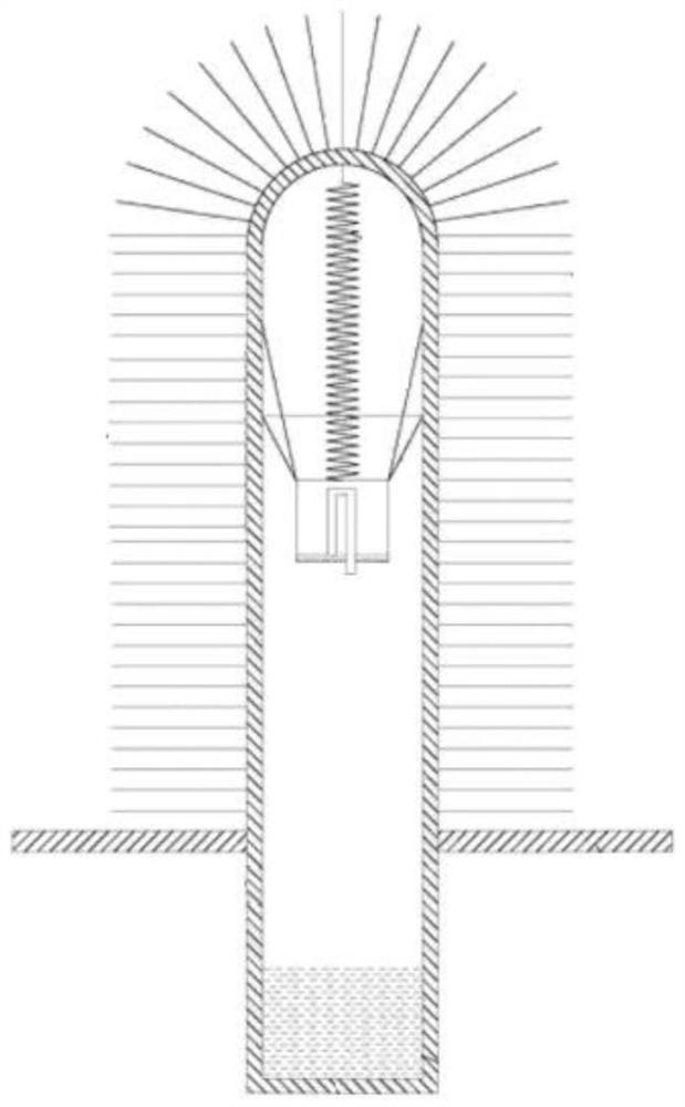
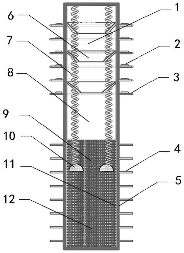
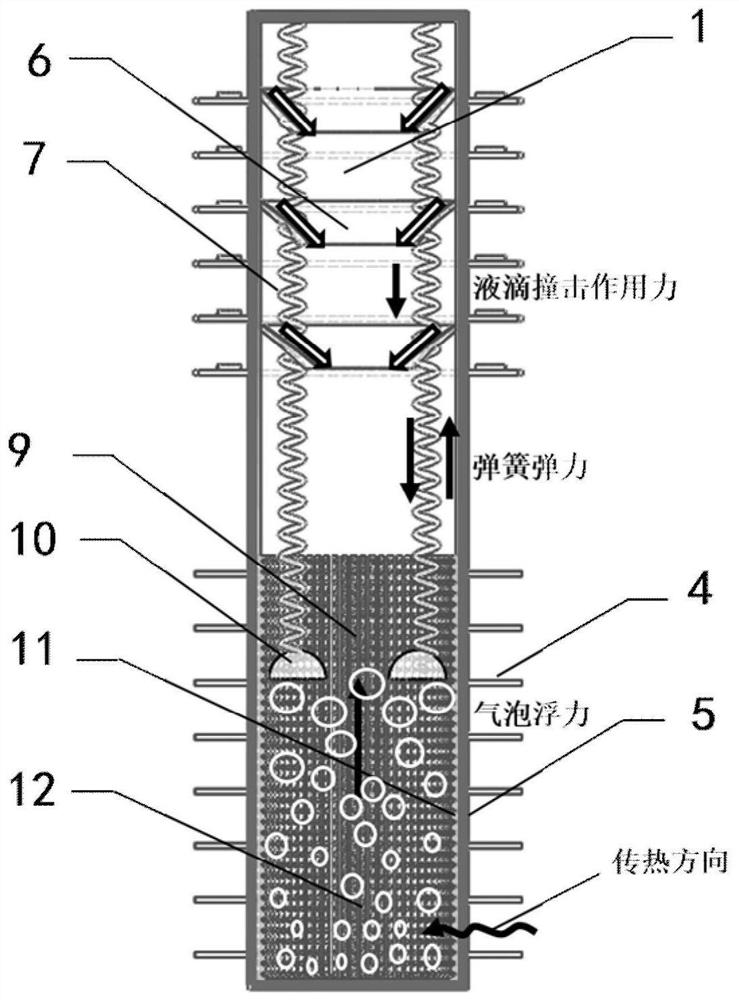
Gravity heat pipe based on dual-power drive enhanced heat transfer
A dual power drive, gravity heat pipe technology, applied in the field of heat pipes, can solve problems such as unreasonable design and layout of the lifting box and return plate, inability to scrape off the liquid film in the condensation section, and hinder the internal gas-liquid circulation of the heat pipe, etc. Mass heat transfer, reduce interaction, and enhance the effect of heat dissipation
- Summary
- Abstract
- Description
- Claims
- Application Information
AI Technical Summary
Problems solved by technology
Method used
Image

Examples
Embodiment Construction
[0035] The following will refer to the attached Figure 1 to Figure 8 Specific embodiments of the present disclosure are described in detail. Although specific embodiments of the present disclosure are shown in the drawings, it should be understood that the present disclosure may be embodied in various forms and should not be limited to the embodiments set forth herein. Rather, these embodiments are provided for more thorough understanding of the present disclosure and to fully convey the scope of the present disclosure to those skilled in the art.
[0036] It should be noted that certain terms are used in the specification and claims to refer to specific components. Those skilled in the art should understand that they may use different terms to refer to the same component. The specification and claims do not use differences in nouns as a way of distinguishing components, but use differences in functions of components as a criterion for distinguishing. "Includes" or "compri...
PUM
 Abstract
Description
Claims
Application Information
 - R&D Engineer
- R&D Manager
- IP Professional
- Industry Leading Data Capabilities
- Powerful AI technology
- Patent DNA Extraction
Browse by: Latest US Patents, China's latest patents, Technical Efficacy Thesaurus, Application Domain, Technology Topic, Popular Technical Reports.
© 2024 PatSnap. All rights reserved.Legal|Privacy policy|Modern Slavery Act Transparency Statement|Sitemap|About US| Contact US: help@patsnap.com