Pump unit for lifting ore pulp in sea, combined structure and mining lifting system

A technology of pump unit and slurry, which is applied to components of pumping devices for elastic fluids, pump elements, mining minerals, etc., and can solve problems such as reliability, low economy, easy fatigue damage of diaphragms, and immature technology , to achieve stable and reliable pulp suction and discharge process, strong economy and feasibility, and simple structure

Active Publication Date: 2021-10-19
SICHUAN HONGHUA PETROLEUM EQUIP
View PDF17 Cites 0 Cited by
  • Summary
  • Abstract
  • Description
  • Claims
  • Application Information

AI Technical Summary

Problems solved by technology

However, the technology is not yet mature enough. The most promising method for deep-sea mining is the hydraulic pipeline lifting method. Even if the ore and seawater are mixed in a certain proportion to form a slurry, the slurry is lifted from the seabed ore collector through the pipeline to the mining ship on the sea surface, such as Patent document A system and method for recoil riser transfer pipe (application number CN201780014682.3), and another example of patent document is a deep-sea mining lift pump (application number CN202010052464.2)
[0004] In the prior art, although the deep-sea centrifugal pumping method improves the mining efficiency to a certain extent, it cannot be completed in one step, and multi-stage transportation is required, and due to the wear of the ore slurry, the blades are easy to wear, the service life is short, and the reliability and economy are not high.
The deep-sea diaphragm pump has a relatively small displacement and a large stroke, the diaphragm is easily damaged by fatigue, and the efficiency is not high enough.

Method used


Image

  • Pump unit for lifting ore pulp in sea, combined structure and mining lifting system
  • Pump unit for lifting ore pulp in sea, combined structure and mining lifting system
  • Pump unit for lifting ore pulp in sea, combined structure and mining lifting system

Examples


Embodiment 1

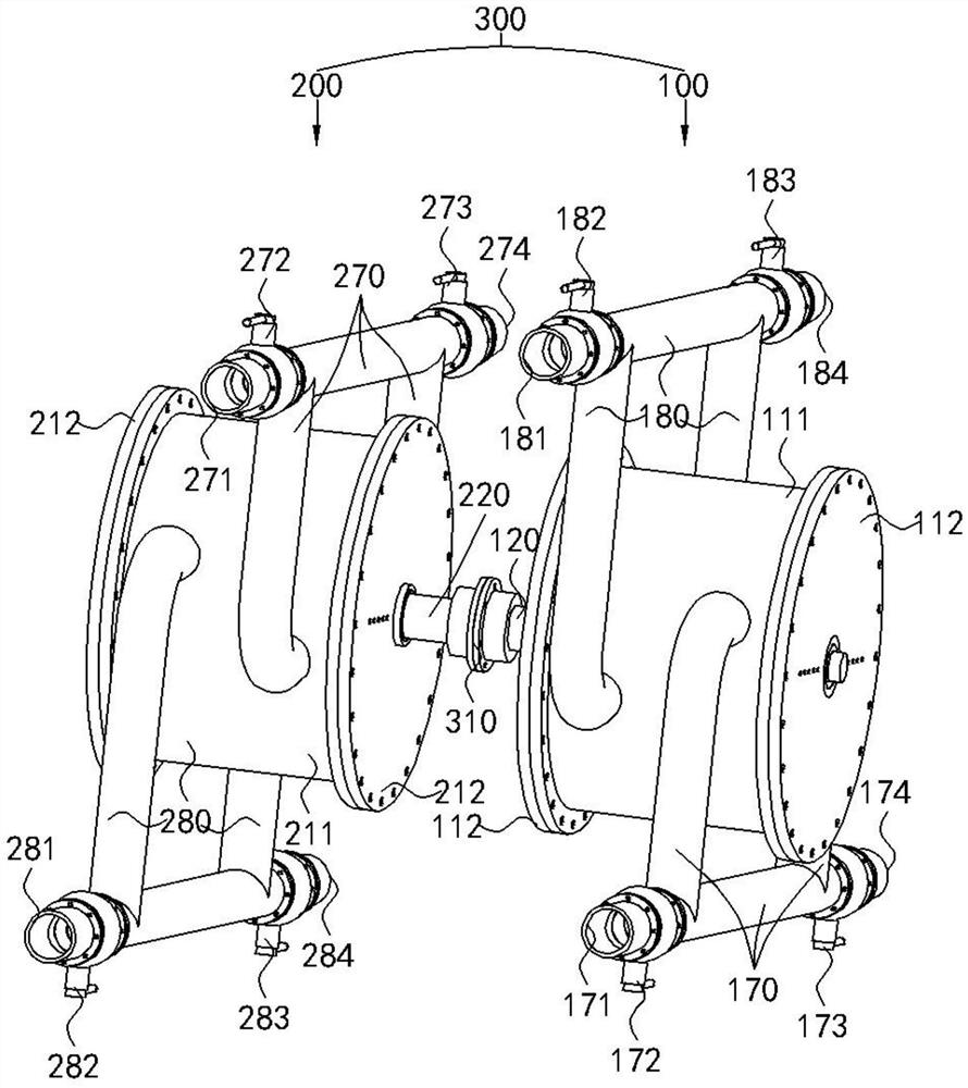
[0061] Such as Figure 1 to Figure 7 As shown, in this embodiment, a pump unit for lifting ore slurry in the sea, the pump unit includes m sets of first pump bodies and n sets of second pump bodies, m≥1, n≥1;

[0062] In each set of first pump bodies, each set of second pump bodies,

[0063] The first pump main body and the second pump main body respectively include a housing, and a coaxial and rotatable rotating shaft assembled in the housing, and through k partitions and k blades, separating the inner cavity of the shell into k seawater cavities and k pulp cavities that are independent and alternately distributed, k≥1; wherein,

[0064] The separator is fixedly and sealingly connected with the inner wall of the housing, and is slidingly and sealingly matched with the rotating shaft, and the blade is fixedly and sealingly connected with the rotating shaft, and is slidingly and sealingly matched with the inner wall of the housing;

[0065] The k seawater cavities are connect...

Embodiment 2

[0086] Based on the first embodiment, in order to facilitate the understanding of the present invention, in the second embodiment, m=n=1, k=2 is taken as an example, that is, there is only one set of the first pump body and the second pump body respectively. In the first pump main body and the second pump main body, there are two clapboards and two vanes in the casing respectively, forming two seawater cavities and two ore slurry cavities which are mutually independent and alternately distributed. The details are as follows.

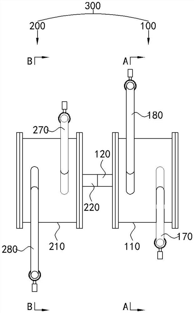
[0087] Such as Figure 1 to Figure 7 As shown, the pump unit of this embodiment includes a set of first pump main body and a set of second pump main body; wherein,

[0088] In the first pump body 100, the first pump body 100 includes a first casing 110 (the first casing 110 includes a first cylinder body 111 and a first end cover 112 sealingly connected to both ends thereof), and coaxial and The first rotating shaft 120 rotatably assembled in the first...

Embodiment 3

[0105] Embodiment 3 is basically the same as Embodiment 2, except that in Embodiment 2, k=2; and in Embodiment 3, k=1. Such as Figure 8 to Figure 11As shown, in the third embodiment, there is only one set of the first pump main body and the second pump main body respectively. In the first pump main body and the second pump main body, there are one partition plate and one vane in the housing respectively. A seawater cavity and a slurry cavity are formed independently of each other. The principle and action process of the third embodiment are the same as those of the second embodiment, and will not be repeated here.

[0106] Embodiment 3 Compared with Embodiment 2, the disadvantage of Embodiment 3 is that, during the operation of the first pump body 100 and the second pump body 200 , the forces are unbalanced and the stability is not strong enough. Therefore, in each set of the first pump body and each set of the second pump body, it is the best choice for k to be an even num...


PUM


Abstract

The invention discloses a pump unit for lifting ore pulp in the sea, a combined structure and a mining lifting system, and belongs to the technical field of lifting equipment for mineral products in the sea. The pump unit for lifting the ore pulp in the sea comprises a first pump body and a second pump body. When high-pressure seawater is poured into a seawater cavity of the first pump body, the ore pulp in an ore pulp cavity of the first pump body can be discharged, seawater in a seawater cavity of the second pump body can be discharged, and the ore pulp can be sucked into an ore pulp cavity of the second pump body. When the high-pressure seawater is poured into the seawater cavity of the second pump body, the ore pulp in the ore pulp cavity of the second pump body can be discharged, the seawater in the seawater cavity of the first pump body can be discharged, and the ore pulp is sucked into the ore pulp cavity of the first pump body. The ore pulp can be continuously sucked into the pump unit and then discharged through continuous reciprocating circulation, and the purpose of lifting the ore pulp in the sea is achieved. The pump unit is large in displacement, long in service life, small in fluctuation, high in efficiency and high in economy and feasibility.

Description

technical field [0001] The invention relates to a pump unit, a combined structure and a mining lifting system for lifting sea ore pulp, belonging to the technical field of sea ore lifting equipment. Background technique [0002] With the continuous mining of terrestrial mineral resources, the depletion of terrestrial mineral resources, and the increasing human demand for minerals, the contradiction between mineral depletion and increased demand has become increasingly prominent, and it is urgent to seek new mineral resources to make up for the shortage of terrestrial mineral resources. Everyone knows that the ocean area accounts for two-thirds of the earth's area, and obtaining new mineral resource increments from the seabed is one of the currently feasible ways. [0003] The ore lifting device is an important part of the deep sea mining system. Its function is to lift the ore from the seabed to the mining ship on the sea surface. At present, it is difficult to lift mineral...

Claims


Application Information

Patent Timeline
Patent Type & Authority Applications(China)
IPC IPC(8): F04D13/12F04D13/04F04D7/00F04D29/40F04D29/18F04D15/00E21C50/02
CPCF04D13/12F04D13/043F04D7/00F04D29/406F04D29/18F04D15/0005E21C50/02
Inventor 文仁强刘放邱雪熊小平
Owner SICHUAN HONGHUA PETROLEUM EQUIP
Why Eureka
Try Eureka