Energy-saving lighting equipment and arrangement system thereof

An energy-saving lighting and equipment technology, applied in lighting and heating equipment, lighting devices, lighting auxiliary devices, etc., can solve the problems of inconvenient replacement and inconvenient adjustment of irradiation angle, and achieve the effect of strong adaptability

Active Publication Date: 2021-10-15
霍明科技(广东)有限公司
View PDF2 Cites 0 Cited by
  • Summary
  • Abstract
  • Description
  • Claims
  • Application Information

AI Technical Summary

Problems solved by technology

[0004]The purpose of the present invention is to provide energy-saving lighting equipment and its arrangement system, to solve the problem that if the lamp tube in the lamp is damaged in the current construction site environment, it is very inconvenient to replace , and the problem of inconvenient adjustment of the irradiation angle

Method used


Image

  • Energy-saving lighting equipment and arrangement system thereof
  • Energy-saving lighting equipment and arrangement system thereof
  • Energy-saving lighting equipment and arrangement system thereof

Examples


Embodiment 1

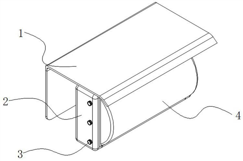
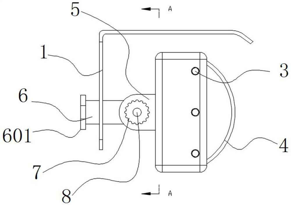
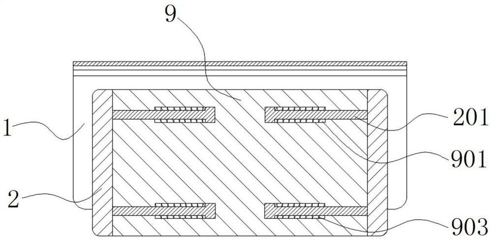
[0037] see Figure 1-7 As shown, the present invention is an energy-saving lighting device, including a rain cover 1, a movable housing 2, a lampshade 4 and a fixed housing 9, the back of the fixed housing 9 is fixedly connected with a U-shaped seat 5, and the U-shaped seat 5 is rotatably fitted with a connecting piece 6. The rain cover 1 is installed on the connecting piece 6, one end of the connecting piece 6 is fixedly connected with the connecting plate 601, the movable shell 2 is located on both sides of the fixed shell 9, and the movable shell 2 and the fixed shell 9 are both located inside the rain cover 1 , the fixed housing 9 is provided with a number of guide grooves 901, the guide grooves 901 are symmetrically distributed with the center line of the fixed housing 9, the guide grooves 901 are slidably connected with the connecting rod 201, and the connecting rod 201 is located at one end of the guide groove 901. The first spring 903 is fixedly connected between the f...

Embodiment 2

[0048] like Figure 12 As shown, the structure of the main bracket 14 does not necessarily need to adopt Figure 11 In the linear form, you can also use Figure 12 In this way, the main support 14 can be installed on a carrier such as a wall, which improves the flexibility of installation.

Embodiment 3

[0050] It should be noted that this device is suitable for outdoor lighting work, such as building construction. In addition, in order to improve the battery life of the lighting device during practical application, a solar battery panel can also be added on the main support 14, depending on actual needs.


PUM


Abstract

The invention discloses energy-saving lighting equipment and an arrangement system thereof, belonging to the technical field of lighting equipment. The energy-saving lighting equipment comprises a rain cover body, a movable shell, a lampshade and a fixed shell, wherein a U-shaped base is fixedly connected to the back face of the fixed shell, the U-shaped base is rotationally matched with a connecting piece, the rain cover body is installed on the connecting piece, and one end of the connecting piece is fixedly connected with a connecting plate. By using the movable shell, the fixed shell and a telescopic part, a lamp tube can be conveniently placed between opposite second ports after the movable shell and the fixed shell are separated during use, and if the lamp tube is slightly long, the lamp tube can be positioned by utilizing the telescopic effect of the telescopic part, so high adaptability is achieved; and therefore, the lamp tube of the lighting equipment can be replaced more conveniently and quickly. By using an adjusting rod, an included angle between the U-shaped base and the connecting piece can be conveniently changed, so the irradiation direction of the lighting equipment is changed.

Description

technical field [0001] The invention belongs to the technical field of lighting equipment, and in particular relates to energy-saving lighting equipment and an arrangement system thereof. Background technique [0002] There are various types of lighting equipment, involving various lamps. Modern lamps include home lighting, commercial lighting, industrial lighting, road lighting, landscape lighting, special lighting, etc. From the birth of electricity, home lighting appeared the earliest incandescent bulbs, and later developed into fluorescent tubes, and then later energy-saving lamps, halogen lamps, tungsten halogen lamps, gas discharge lamps and LED lighting with special materials and so on. In the construction industry, it is often necessary to work at night, so a large number of lamps need to be used. In order to save energy, LED lamps are generally used. [0003] However, in the construction environment of the construction site, if the lamp tube in the lamp is damaged...

Claims


Application Information

Patent Timeline
Patent Type & Authority Applications(China)
IPC IPC(8): F21S8/08F21V19/02F21V21/14
CPCF21S8/086F21V19/02F21V21/14
Inventor 王娟魏健健刘爱丽
Owner 霍明科技(广东)有限公司
Why Eureka
Try Eureka