Automatic equipment applied to ultraviolet LED lamp processing

A technology of automation equipment and LED lamps, which is applied to the device and coating of the surface coating liquid, which can solve the problems of inability to inject glue and compaction, low efficiency, and decreased radiation intensity of devices, so as to improve work efficiency and stability , reduce manufacturing costs, and improve injection efficiency

Pending Publication Date: 2021-10-15
ZHONGSHAN MULINSEN ELECTRONICS CO LTD
View PDF5 Cites 0 Cited by
  • Summary
  • Abstract
  • Description
  • Claims
  • Application Information

AI Technical Summary

Problems solved by technology

[0002] Silicone used in ultraviolet LED lamp beads will accelerate aging and attenuation when exposed to ultraviolet light. The use of inorganic packaging can effectively reduce the speed of LED aging and attenuation; most of the lenses and substrates are bonded with silicone adhesives, while organic The short-wave high-energy ultraviolet light excitation of the material during the long-term service will accelerate the oxidation, and the performance will deteriorate, which will eventually lead to a decrease in the radiation intensity of the device;
[0003] The traditional assembly method uses manual processing, which has low efficiency, high cost, and waste of manpower and material resources. Therefore, for the specific product of the present invention, it is necessary to redesign an automatic production machine with high efficiency, low equipment cost, more flexibility, and continuous work. equipment, and the glue injection efficiency is slow, it is impossible to fully compress the glue injection, it is easy to generate air bubbles, and the sealing is poor

Method used


Image

  • Automatic equipment applied to ultraviolet LED lamp processing
  • Automatic equipment applied to ultraviolet LED lamp processing
  • Automatic equipment applied to ultraviolet LED lamp processing

Examples


Embodiment Construction

[0031] The following will clearly and completely describe the technical solutions in the embodiments of the present invention with reference to the accompanying drawings in the embodiments of the present invention. Obviously, the described embodiments are only some, not all, embodiments of the present invention. Based on the embodiments of the present invention, all other embodiments obtained by persons of ordinary skill in the art without making creative efforts belong to the protection scope of the present invention.

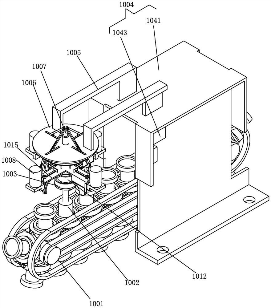
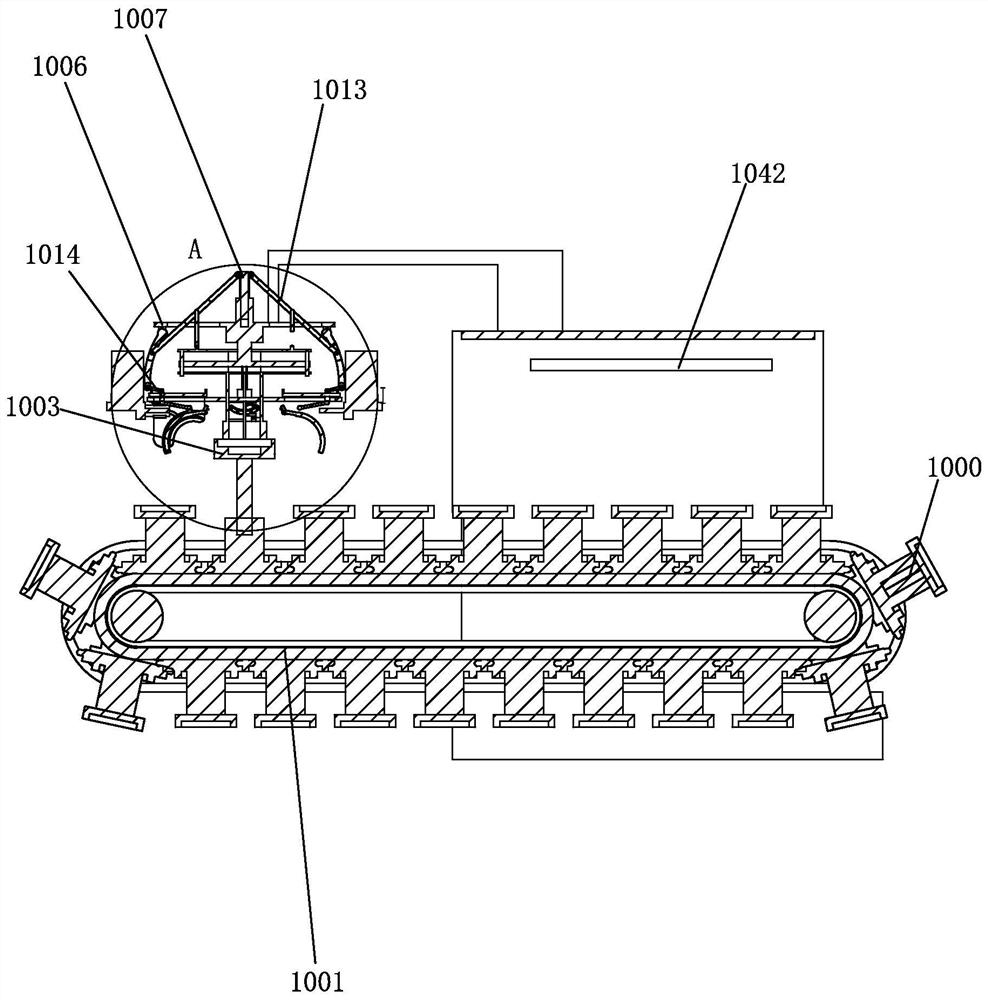
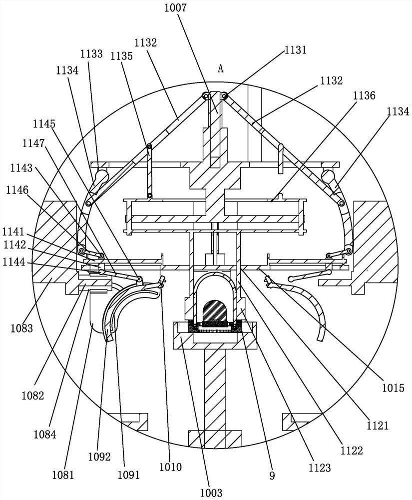
[0032] see Figure 1-10 , the present invention provides

[0033] An inorganic packaged ultraviolet LED lamp, comprising a substrate 1, on which an LED chip assembly 2 is arranged, the LED chip assembly 2 is wrapped with an inorganic material 3 for packaging, and the substrate 1 is provided with a lens mounting groove 4 A lens body 5 is installed in the lens installation groove 4, a plurality of first inner grooves 6 are provided on the inner and outer surfac...


PUM


Abstract

The invention discloses automatic equipment applied to ultraviolet LED lamp processing. The automatic equipment comprises a conveying track, a plurality of lifting devices are arranged on the conveying track, a lamp set mounting base is arranged on the lifting devices, an upper top plate is arranged on a support, a lifting mechanism is arranged on the upper top plate, and a lower bottom plate is arranged below the upper top plate in a spaced mode. An LED chip assembly 2 and a lens body are automatically fed to the stations of a glue injection device and a pressing device, comprehensive glue injection action is done, one-time synchronous glue injection is achieved on multiple parts, the glue injection efficiency is improved, after glue injection is completed, the connecting rod assembly can be controlled by turns to be switched to the pressing mode, and the glue injection assembly automatically gives way. And moreover, the pressing assembly and the glue injection assembly do not interfere with each other, the working efficiency and stability are further improved, the pressing assembly is arranged, internal injected glue can be prevented from generating bubbles, meanwhile, it can be guaranteed that the injected glue is tightly attached to the surface of a product, and the sealing performance is improved.

Description

technical field [0001] The invention relates to ultraviolet LED lamp processing equipment, in particular to an automatic equipment applied to ultraviolet LED lamp processing. Background technique [0002] Silicone used in ultraviolet LED lamp beads will accelerate aging and attenuation when exposed to ultraviolet light. The use of inorganic packaging can effectively reduce the speed of LED aging and attenuation; most of the lenses and substrates are bonded with silicone adhesives, while organic The short-wave high-energy ultraviolet light excitation of the material during the long-term service will accelerate the oxidation, and the performance will deteriorate, which will eventually lead to a decrease in the radiation intensity of the device; [0003] The traditional assembly method uses manual processing, which has low efficiency, high cost, and waste of manpower and material resources. Therefore, for the specific product of the present invention, it is necessary to redesig...

Claims


Application Information

Patent Timeline
IPC IPC(8): B05C5/02B05C13/02B05C11/10
CPCB05C5/0208B05C13/02B05C11/1002
Inventor 石红丽
Owner ZHONGSHAN MULINSEN ELECTRONICS CO LTD
Why Eureka
Try Eureka