Vertical shaft wind power generation equipment

A wind power generation equipment and vertical shaft technology, which is applied in the field of vertical shaft wind power generation equipment, can solve the problems of inability to stop the rotation of the generator blades in time, adjust the height of the power generation blades, and tip over, so as to prevent jamming, improve efficiency, and reduce the possibility of damage. Effect

Pending Publication Date: 2021-10-12
ANHUI UNIV OF SCI & TECH
View PDF0 Cites 0 Cited by
  • Summary
  • Abstract
  • Description
  • Claims
  • Application Information

AI Technical Summary

Problems solved by technology

In daily life, in addition to large and common windmill generators, there are also some small outdoor wind turbines, but most of the small generators are prone to tipping or damage to the support rods due to excessive wind force , the common wind power generation equipment cannot timely adjust the height of the power generation blades according to the wind force, and the risk of tipping is low, and the rotation of the generator blades cannot be stopped in time when the wind force is extremely strong and it is not suitable for the power generation equipment to continue to work

Method used


Image

  • Vertical shaft wind power generation equipment
  • Vertical shaft wind power generation equipment
  • Vertical shaft wind power generation equipment

Examples


Embodiment Construction

[0023] In order to make the technical means, creative features, goals and effects achieved by the present invention easy to understand, the present invention will be further described below in conjunction with specific embodiments.

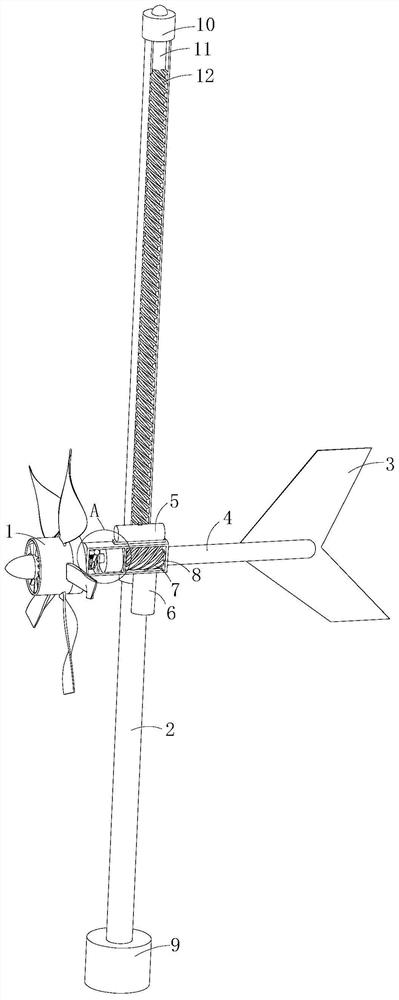
[0024] Such as Figure 1-Figure 7 As shown, a vertical axis wind power generation device according to the present invention includes a generator main body 1, a shaft rod 2, a tail blade 3, an operating room 8, a counterweight rod 4, a rotating base 9, a gear mechanism, a braking mechanism and Lubricating mechanism, the top of the shaft 2 is welded with a stopper 10, which is used to limit the rising stroke of the power generation equipment. There is a groove 11 on one side of the shaft 2 close to the bottom of the stopper 10. There is no helical tooth 12 in the groove 11. When the worm 7. When it slides into the groove 11 and cannot continue to mesh, it will stop rising. There is a helical tooth 12 under the groove 11 to provide a track for the wo...


PUM


Abstract

The invention relates to the field of wind power generation, in particular to vertical shaft wind power generation equipment. The equipment comprises a generator body, a shaft rod, tail blades, an operation chamber, a balance weight rod, a base, a gear moving mechanism, a braking mechanism and a lubricating mechanism. A check block is welded to the top end of the shaft rod, a groove is formed in the position, close to the lower portion of the check block, of one side of the shaft rod, and spiral teeth are arranged below the groove. A sliding groove is formed in the other side of the shaft rod, a sliding cylinder is slidably connected to the shaft rod, the operation chamber is fixed to one side of the sliding cylinder, a pulley is coupled to the top of the side, away from the operation chamber, of the sliding cylinder, the pulley is slidably connected to the interior of the sliding groove, the operation chamber is connected with the gear moving mechanism, and a generator body is installed at one end of the operation chamber. The balance weight rod is mounted at the other end of the operation chamber, the braking mechanism is mounted on one side of the interior of the operation chamber, and the lubricating mechanism is mounted on the other side of the interior of the operation chamber. According to the vertical shaft wind power generation equipment, the height of power generation blades can be adjusted according to wind power.

Description

technical field [0001] The invention relates to the field of wind power generation, in particular to vertical shaft wind power generation equipment. Background technique [0002] The principle of wind power generation is to use wind power to drive the windmill blades to rotate, and then increase the speed of rotation through the speed increaser to promote the generator to generate electricity; while wind power generation equipment converts wind energy into mechanical work, which drives the rotor to rotate, and finally Electrical equipment that outputs alternating current. In the northeast, northwest, southwest plateaus and coastal islands, places with high average wind speed are very common; and the power of generator models is different, and the application scenarios are also different. In daily life, in addition to large and common windmill generators, there are also some small outdoor wind turbines, but most of the small generators are prone to tipping or damage to the s...

Claims


Application Information

Patent Timeline
IPC IPC(8): F03D9/25F03D1/06F03D13/20F03D15/00F03D80/00F03D80/70
CPCF03D9/25F03D15/00F03D80/70F03D13/20F03D80/00F03D1/0658Y02E10/728Y02E10/72
Inventor 徐鹏郭奋昊
Owner ANHUI UNIV OF SCI & TECH
Why Eureka
Try Eureka