
Device for eliminating cable connecting line errors

A connection line and error technology, which is applied in the field of cable connection line error elimination device, can solve the problems of large demand for human resources, displacement of filling layer, etc., and achieve the effects of saving human resources, eliminating connection errors, and improving efficiency

Pending Publication Date: 2021-10-08
李不畏
View PDF0 Cites 0 Cited by
  • Summary
  • Abstract
  • Description
  • Claims
  • Application Information

AI Technical Summary

Problems solved by technology

[0006] The invention provides a device for eliminating errors of cable connection lines, one of which is to have a positioning function to solve the traditional cable connection work. After cutting the skin of the outer surface, the exposed filling layer is easy to appear during the connection process. The problem of displacement phenomenon; another purpose is to solve the traditional cable wiring work. When encountering cables with larger diameters, the demand for human resources is large, so as to improve wiring efficiency and save human resources.

Method used


Image

  • Device for eliminating cable connecting line errors
  • Device for eliminating cable connecting line errors
  • Device for eliminating cable connecting line errors

Examples


Embodiment 1

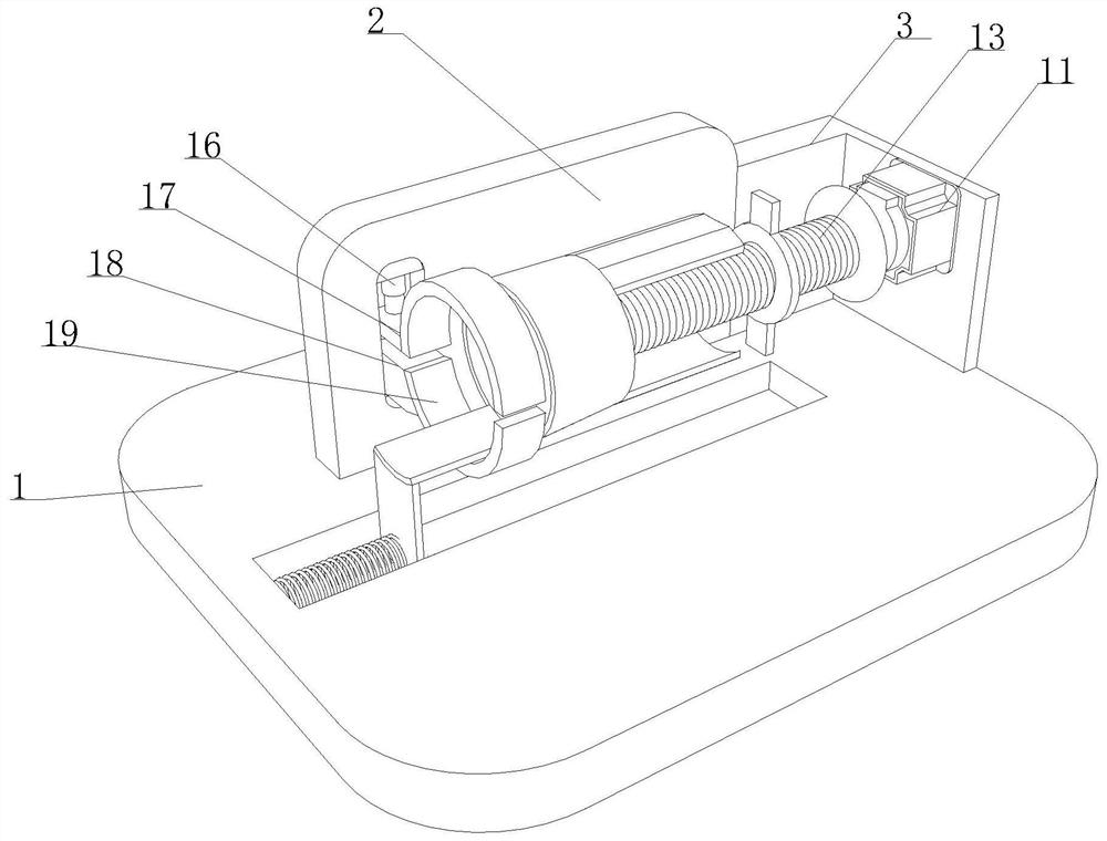
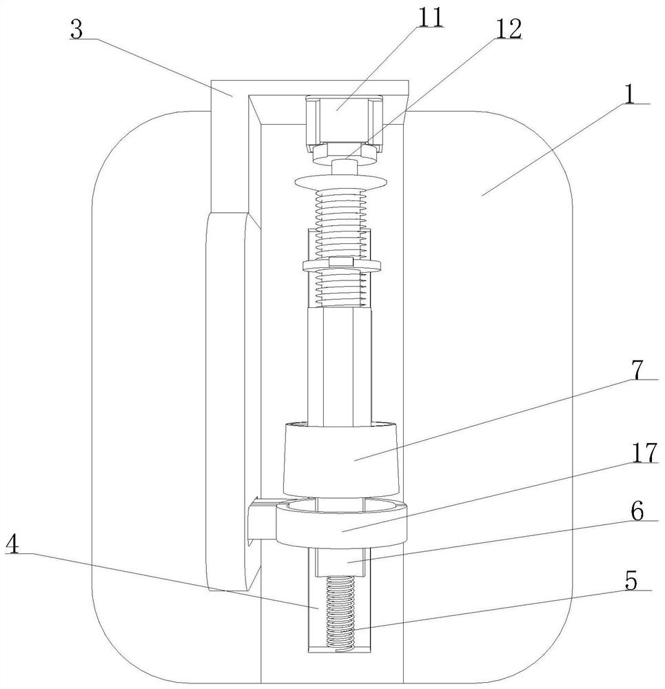
[0035] Such as Figure 1-8 As shown, the present invention provides a device for eliminating cable connection errors, including a connecting base 1 and a positioning arm 2 and a fixing frame 3 arranged on the top thereof. The right side of the inner wall is movably connected with a sliding limiter 6 by being provided with a connecting spring 5, the sliding limiter 6 is arranged in an inverted L shape, and the right end of the sliding limiter 6 is provided with a positioning mechanism 7, and the device for eliminating cable connection errors is During use, under the elastic action of the connecting spring 5, the sliding limit frame 6 can move inside the limit groove 4, and in the process of moving, it can drive the positioning mechanism 7 provided at its right end to perform synchronous movement.

[0036] Further, the positioning mechanism 7 includes an upper arc-shaped frame body 71, a lower arc-shaped frame body 72, an inner support plate 73 and a processing ring 74, and the ...

Embodiment 2

[0038] Such as Figure 1-8As shown, on the basis of Embodiment 1, the present invention provides a technical solution: preferably, the inner surfaces of the upper arc-shaped frame body 71 and the lower arc-shaped frame body 72 are all provided with positioning grooves 75, and the inner surfaces of the positioning grooves 75 The cavity is provided with a processing ring 74, and the processing ring 74 includes an arc-shaped shrapnel 1 741, an arc-shaped shrapnel 2 742 and a friction ring 743. 1. The arc-shaped shrapnel 2 742 is arranged in an inverted X shape, and the end of the arc-shaped shrapnel 742 is fixedly connected with a friction ring 743, and the arc-shaped shrapnel 1 741 and the arc-shaped shrapnel 2 742 that are arranged in an inverted X-shape inside the positioning groove 75 Under the elastic force of the cable, the friction ring 743 can press the exposed filling part of the cable to increase its connection force. Under the elastic force of the connection spring 5, ...

Embodiment 3

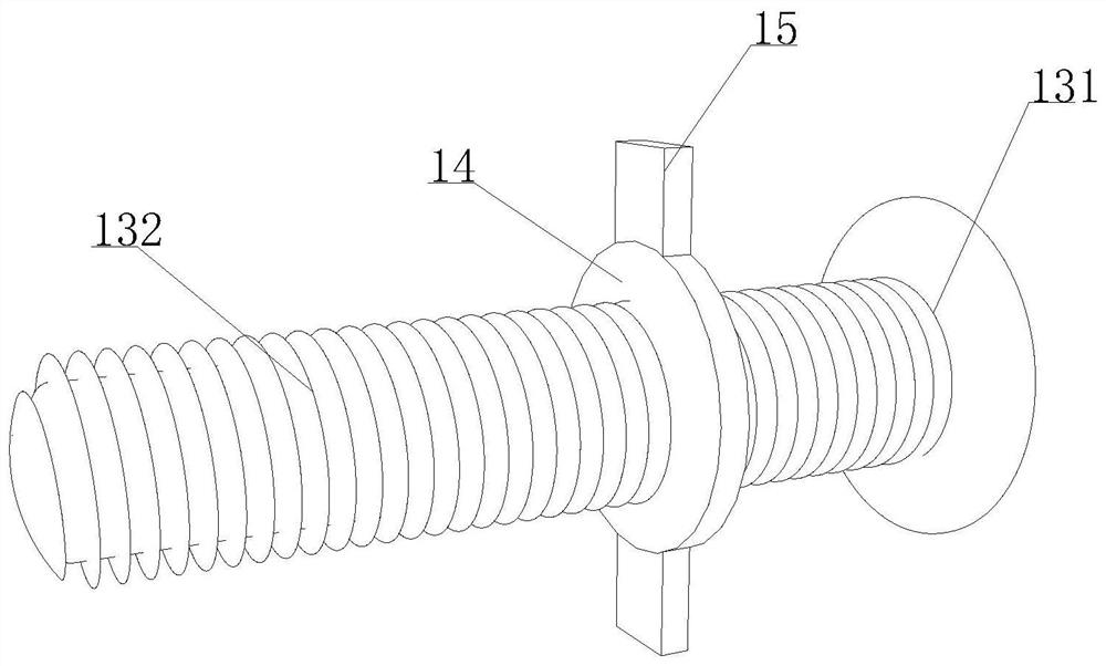
[0041] Such as Figure 1-8 As shown, on the basis of Embodiment 1, the present invention provides a technical solution: preferably, the right side of the positioning arm 2 is fixedly connected to the left side of the fixed frame 3, and the left side of the fixed frame 3 is provided with a power driver 11 , the output end of the power driver 11 is movably connected with a power threaded rod 13 by being provided with a transmission rod 12, the outer surface of the power threaded rod 13 is detachably connected with a rotating ring 14, and the top and bottom of the rotating ring 14 are provided with a push frame 15 , to control the operation of the power driver 11, under the transmission action of the transmission rod 12 provided at the output end of the power driver 11, the power threaded rod 13 movably connected with it rotates, and the rotating ring 14 arranged on the outer surface of the power threaded rod 13 and the driving force The frame 15 can move close to the inner suppo...


PUM


Abstract

The invention discloses a device for eliminating cable connecting line errors, and relates to the technical field of cable processing, the device comprises a connecting seat, and a positioning arm and a fixing frame which are arranged at the top of the connecting seat, the top of the connecting seat is provided with a limiting groove, and the right side of the inner wall of the limiting groove is movably connected with a sliding limiting frame by arranging a connecting spring; and the sliding limiting frame is arranged in an inverted-L shape, a positioning mechanism is arranged at the right end of the sliding limiting frame, and the positioning mechanism comprises an upper arc-shaped frame body, a lower arc-shaped frame body, an inner supporting plate and a processing ring. The phenomenon of displacement of a filling layer during wiring is effectively avoided, connecting errors caused by displacement of the filling layer are further effectively eliminated, the efficiency of wiring work is improved, manpower resources are effectively saved, the situation that the filling layer of the cable is dragged out in the moving process of the cable is effectively avoided, and the filling layer of the cable can be connected more tightly in the process of being gradually sleeved by the connecting ring, so that the slipping phenomenon of the cable is effectively avoided.

Description

technical field [0001] The invention relates to the technical field of cable processing, in particular to a device for eliminating errors of cable connecting lines. Background technique [0002] A cable is made of one or more mutually insulated conductors and an outer insulating layer, which transmits power or information from one place to another, or consists of several or groups of conductors (at least two in each group) A stranded, rope-like cable in which each set of conductors are insulated from each other and are usually twisted around a center, with a highly insulating covering covering the entire outside. The cable has the characteristics of internal energization and external insulation. During the laying of the cable, it is necessary to carry out wiring work on the cable to ensure the smooth flow of the circuit. [0003] There are following problems at prior art: [0004] 1. In the traditional cable wiring work, after the outer skin is cut, the exposed filling lay...

Claims


Application Information

Patent Timeline
Patent Type & Authority Applications(China)
IPC IPC(8): H01R43/28
CPCH01R43/28
Inventor 李不畏
Owner 李不畏
Learn More