
Polygonal heating furnace and using method thereof

A polygonal heating furnace technology, applied in the field of heating furnaces, can solve the problems of large floor space, lax furnace door closing, heavy workload, etc., and achieve the effects of convenient installation and disassembly, convenient installation and disassembly, and fast heating speed.

Pending Publication Date: 2021-10-08
CHINA UNITED EQUIP GRP ANYANG MASCH CO LTD
View PDF0 Cites 0 Cited by
  • Summary
  • Abstract
  • Description
  • Claims
  • Application Information

AI Technical Summary

Problems solved by technology

[0002] In the prior art, the shape of the heating furnace is mostly square or round, and the furnace door adopts the structure of the rotating shaft or the left and right push-pull type, which has the advantages of large floor space, uncompact structure, small effective use of space, and uneven heating of the heating object. Disadvantages such as large heat loss, and prone to problems such as lax door closure and high heat loss
In addition, when the existing workpieces are put in and out of the furnace, the furnace door is usually opened, the workpiece is transported into the furnace, and then the furnace door is closed separately. When the furnace is discharged, the furnace door is opened first, and then the workpiece is transported out of the furnace.
[0003] The main feature of thermal charging of sheet-shaped annular workpieces is multi-piece heating and single-piece installation, that is, multiple workpieces are stacked horizontally in the heating box for heating, and then one piece is taken out for hot charging. This method has the disadvantages of uneven heating of the workpieces, Disadvantages such as large workload, low efficiency, high cost, etc.

Method used


Image

  • Polygonal heating furnace and using method thereof
  • Polygonal heating furnace and using method thereof
  • Polygonal heating furnace and using method thereof

Examples


Embodiment 1

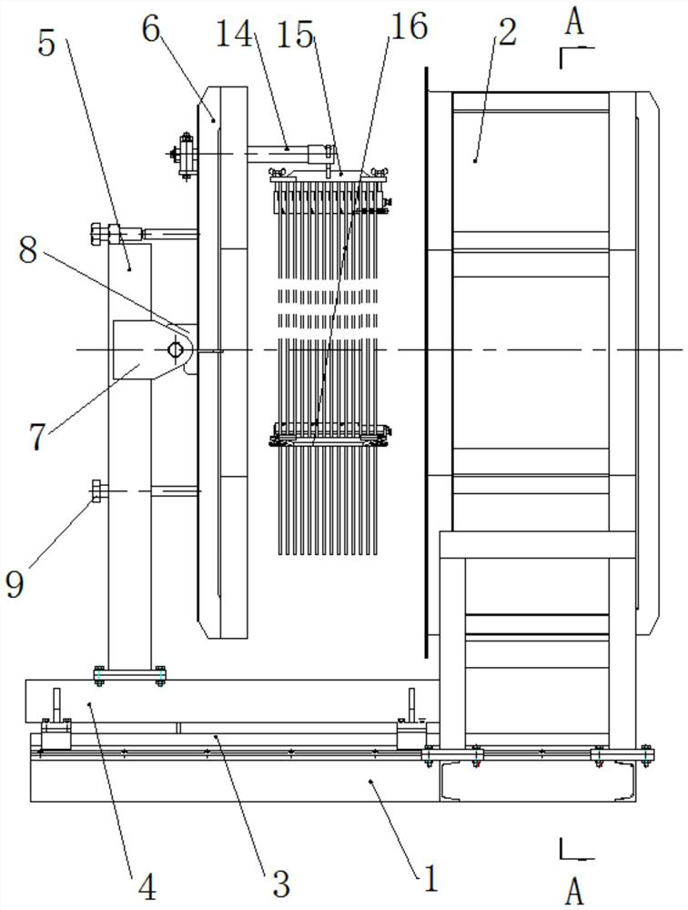
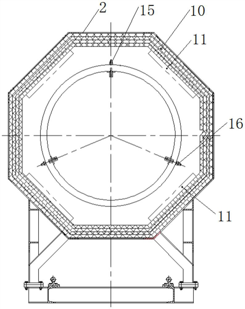
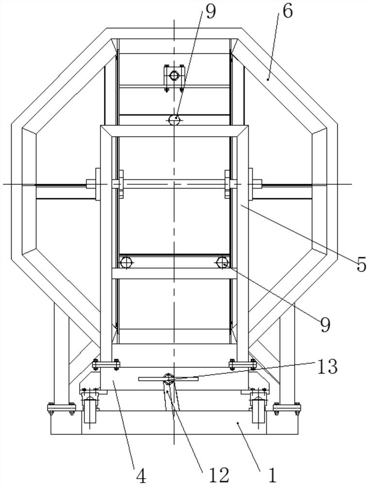
[0035] Such as Figure 1-3 As shown, a polygonal heating furnace includes a furnace base 1, two linear guide rails 3 are arranged on the upper side of the furnace base 1, and a polygonal furnace 2 is arranged on one end of the upper side of the linear guide rail 3, and the linear guide rail 3 is arranged along the axis of the furnace 2 The other end of the upper side of the linear guide rail 3 is provided with a sliding furnace door seat 4, and both sides of the lower end of the furnace door seat 4 are fixed with sliding seats. The sliding seat moves along the linear guide rail 3, and the lower end of the furnace 2 is fixed with a bracket. The bracket is fixedly connected with the furnace base 1 , and the lower end of the furnace 2 and the upper side of the linear guide rail 3 are spaced apart to provide space for the movement of the furnace door seat 4 .

[0036] The upper end of the furnace door seat 4 is fixed with a furnace door bracket 5, which is connected to a polygonal...

Embodiment 2

[0041] This embodiment is basically the same as Embodiment 1, the difference is that, as figure 1 and 4 As shown, the workpiece mounting mechanism includes a mounting rod 14 and a fixed-distance gripper, and the fixed-distance gripper includes a first-type gripper 15 and several second-type grippers 16, and the mounting rod 14 is fixed on the furnace door 6 Above, the first-type clamper 15 is suspended on the mounting rod 14, and the first-type clamper 15 and several second-type clampers 16 are evenly distributed along the circumferential direction of the sheet-shaped annular workpiece.

[0042] Such as Figure 5 and 6 As shown, the first-type clamper 15 and the second-type clamper 16 both include two comb-shaped positioning plates 15-1 arranged at intervals, and a comb-shaped clamping plate is slidingly arranged between the two comb-shaped positioning plates 15-1 15-2, the comb-shaped positioning plate 15-1 includes a first strip-shaped body 15-3, the upper end of the firs...

Embodiment 3

[0050] A method for using a polygonal heating furnace, comprising the following steps:

[0051] (1) Install the workpiece on the workpiece mounting mechanism, move the furnace door 6 to the furnace 2 along the linear guide rail 3, and at the same time, the furnace door 6 drives the workpiece into the furnace 2;

[0052] (2) Then turn 3 adjusting bolts to make the furnace door 6 fully contact with the sealing surface of the furnace 2, and complete the closing of the furnace door 6;

[0053] (3) After the heating of the workpiece is completed, the furnace door 6 is reversely moved along the linear guide rail 3, and then the workpiece is removed from the workpiece mounting mechanism.

[0054] Further, in step (1), the workpiece is mounted on the workpiece mounting mechanism, and the specific steps are as follows:

[0055] 1) First install the fixed-distance holder: pass the comb-shaped positioning plate 15-1 through the shaft holes of multiple sheet-shaped ring workpieces, and p...


PUM


Abstract

The invention provides a polygonal heating furnace and a using method thereof. The polygonal heating furnace comprises a hearth base; a linear guide rail is arranged on the upper side of the hearth base; a polygonal hearth is arranged at one end of the upper side of the linear guide rail; a sliding furnace door base is arranged at the other end of the upper side of the linear guide rail; the linear guide rail is arranged in the axial direction of the hearth; a furnace door support is arranged at the upper end of a furnace door seat; a plurality of adjusting bolts are in threaded connection with the furnace door support; a polygonal furnace door is rotationally connected to the sides, close to the hearth, of the adjusting bolts; a workpiece hanging mechanism is arranged on the side, close to the hearth, of the furnace door; and heating elements are evenly distributed on the inner wall of the hearth in the circumferential direction. The polygonal heating furnace is small in occupied space, compact in structure and high in efficiency, and workpieces enter and exit from the furnace synchronously along with movement of the furnace door.

Description

technical field [0001] The invention relates to the technical field of heating furnaces, in particular to a polygonal heating furnace and its usage method. Background technique [0002] In the prior art, the shape of the heating furnace is mostly square or round, and the furnace door adopts the structure of the rotating shaft or the left and right push-pull type, which has the advantages of large floor space, uncompact structure, small effective use of space, and uneven heating of the heating object. There are disadvantages such as large heat loss, and it is prone to problems such as lax closing of the furnace door and high heat loss. In addition, when the existing workpieces are put in and out of the furnace, the furnace door is usually opened, the workpiece is transported into the furnace, and then the furnace door is closed separately. When the furnace is released, the furnace door is opened first, and then the workpiece is transported out of the furnace. . [0003] The...

Claims


Application Information

Patent Timeline
Patent Type & Authority Applications(China)
IPC IPC(8): F27B17/00F27D1/18F27D3/00
CPCF27B17/00F27D1/1858F27D3/00
Inventor 鲁省龙王院利黄绍民康艳平许俊佳范瑞珍
Owner CHINA UNITED EQUIP GRP ANYANG MASCH CO LTD
Learn More