Lower limb varicose vein rehabilitation treatment system for vascular surgery nursing and method
A technology for varicose veins and rehabilitation treatment, applied in physical therapy, dentistry, dental chair, etc., can solve the problems of inability to cooperate with physical rehabilitation treatment, single function, simple structure, etc., to achieve good rehabilitation treatment effect, better use comfort, The effect of promoting the recovery of varicose veins
- Summary
- Abstract
- Description
- Claims
- Application Information
AI Technical Summary
Problems solved by technology
Method used
Image
Examples
Embodiment 1
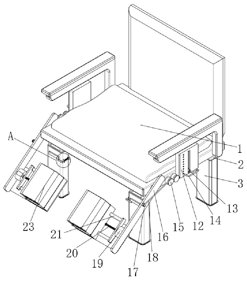
[0040] A system and method for rehabilitation treatment of varicose veins of lower extremities for vascular surgery nursing in this embodiment, such as figure 1 As shown, including the seat main body 1, the four corners of the bottom surface of the seat main body 1 are welded with main legs 2, and the surface of the main leg 2 is equipped with an adjustment mechanism. Connection, the surface of the connecting rod 16 is equipped with a reciprocating motor 19, the output end of the reciprocating motor 19 is fixedly connected with a transmission rod 20, the surface of the transmission rod 20 is provided with a U-shaped transmission part 21 through a threaded sleeve, and the surface of the connecting rod 16 is welded There is a first cover plate 22;
[0041] Such as figure 1As shown, one end of the U-shaped transmission member 21 extends through the first cover plate 22 to the inside of the first cover plate 22, the bottom surface of the first cover plate 22 is hinged with the se...
Embodiment 2
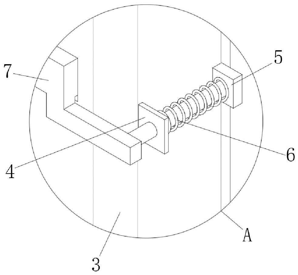
[0044] Such as figure 2 As shown, the adjustment mechanism includes an auxiliary outrigger 3, the bottom end of the main outrigger 2 is covered with an auxiliary outrigger 3, the surface of the main outrigger 2 is equidistantly provided with grooves, and the surface of the auxiliary outrigger 3 is welded with a stopper 4 , the surface of the limiting piece 4 is inserted with a sliding rod 5, the surface of the sliding rod 5 is sleeved with a return spring 6, one end of the returning spring 6 is welded to the surface of the limiting piece 4, and one end of the sliding rod 5 is welded There is a pin 7 , and one end of the pin 7 close to the surface of the auxiliary leg 3 passes through the auxiliary leg 3 and extends into the groove provided on the surface of the main leg 2 .
[0045] When the user needs to adjust the height of the seat body 1, the user only needs to pull out the latch 7 from the main leg 2 and the auxiliary leg 3 in sequence, and the movement of the latch 7 wi...
Embodiment 3
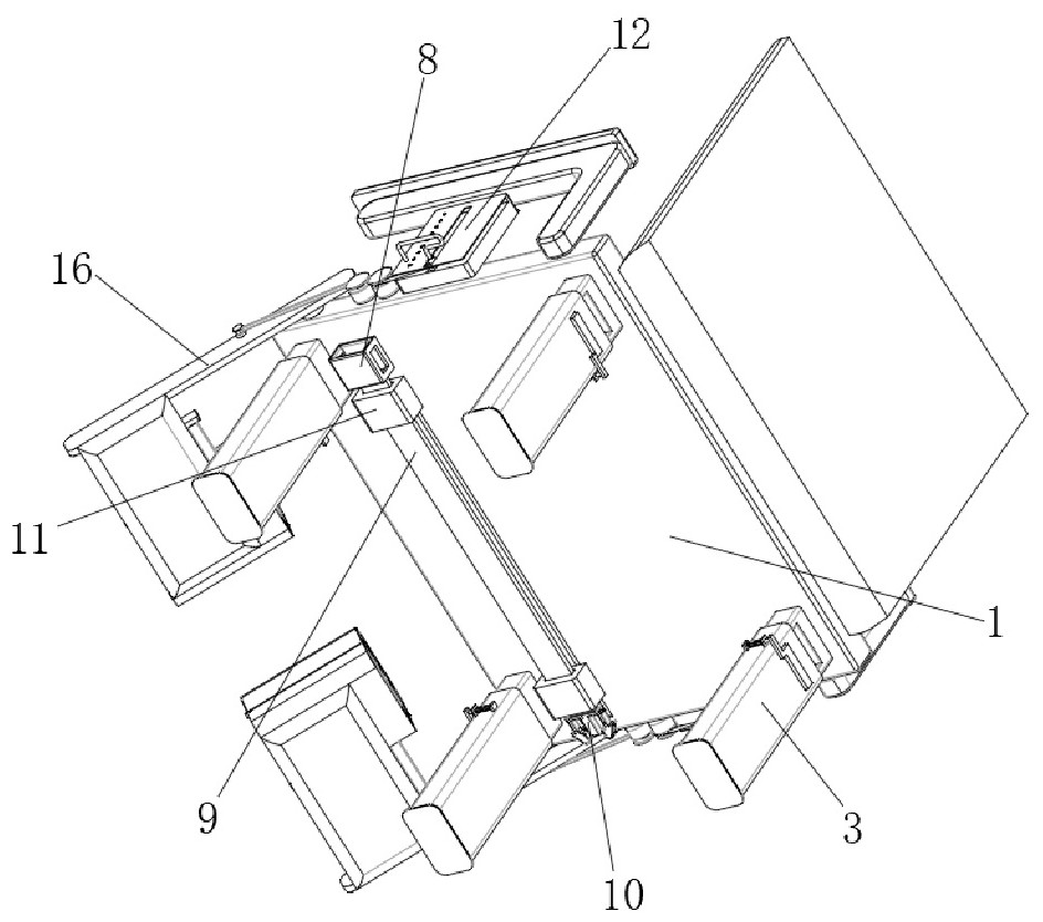
[0051] Such as figure 1 As shown, the motion adjustment mechanism includes a transmission chamber 12, and the two sides of the seat body 1 are symmetrically welded with the transmission chamber 12, and the inside of the transmission chamber 12 is provided with a chute, and the transmission chamber 12 is slidably connected with a sliding block 13 through the chute provided inside. , one end of the sliding block 13 is inserted with a T-shaped handle 14, the surface of the transmission compartment 12 is equally spaced with holes matching the T-shaped handle 14, and the surface of the seat body 1 is symmetrically connected with two groups of first shafts through bearings 15. The surface of the seat main body 1 is symmetrically connected with a connecting rod 16 through a bearing, and the surface of the connecting rod 16 is connected with a second shaft 17 through a rotating shaft. The surface of the second shaft 17 is covered with a transmission belt 18, and the transmission belt 1...
PUM
 Abstract
Description
Claims
Application Information
 - R&D Engineer
- R&D Manager
- IP Professional
- Industry Leading Data Capabilities
- Powerful AI technology
- Patent DNA Extraction
Browse by: Latest US Patents, China's latest patents, Technical Efficacy Thesaurus, Application Domain, Technology Topic, Popular Technical Reports.
© 2024 PatSnap. All rights reserved.Legal|Privacy policy|Modern Slavery Act Transparency Statement|Sitemap|About US| Contact US: help@patsnap.com


