Power output system

A power output and cable technology, applied in the field of power output equipment, can solve problems such as affecting the combat capability of equipment, and achieve the effect of improving efficiency

Pending Publication Date: 2021-10-01
JIANGXI QINGHUA TAIHAO SANBO ELECTRICAL MACHINE
View PDF0 Cites 0 Cited by
  • Summary
  • Abstract
  • Description
  • Claims
  • Application Information

AI Technical Summary

Problems solved by technology

Especially for high-power power stations (above 1MW), there are even more than 100 connecting cables between the equipment. According to the traditional design, personnel have to go back and forth between the power station and the power equipment many times, and each time they can only drag 2 cables. The entire deployment time exceeds 30 minutes, seriously affecting the combat capability of the equipment

Method used


Image

  • Power output system
  • Power output system
  • Power output system

Examples


Embodiment Construction

[0026] In order to make the purpose, technical solutions and advantages of the embodiments of the present invention clearer, the technical solutions in the embodiments of the present invention will be clearly and completely described below in conjunction with the drawings in the embodiments of the present invention. Obviously, the described embodiments It is a part of embodiments of the present invention, but not all embodiments. The components of the embodiments of the invention generally described and illustrated in the figures herein may be arranged and designed in a variety of different configurations.

[0027] Accordingly, the following detailed description of the embodiments of the invention provided in the accompanying drawings is not intended to limit the scope of the claimed invention, but merely represents selected embodiments of the invention. Based on the embodiments of the present invention, all other embodiments obtained by persons of ordinary skill in the art wi...


PUM


Abstract

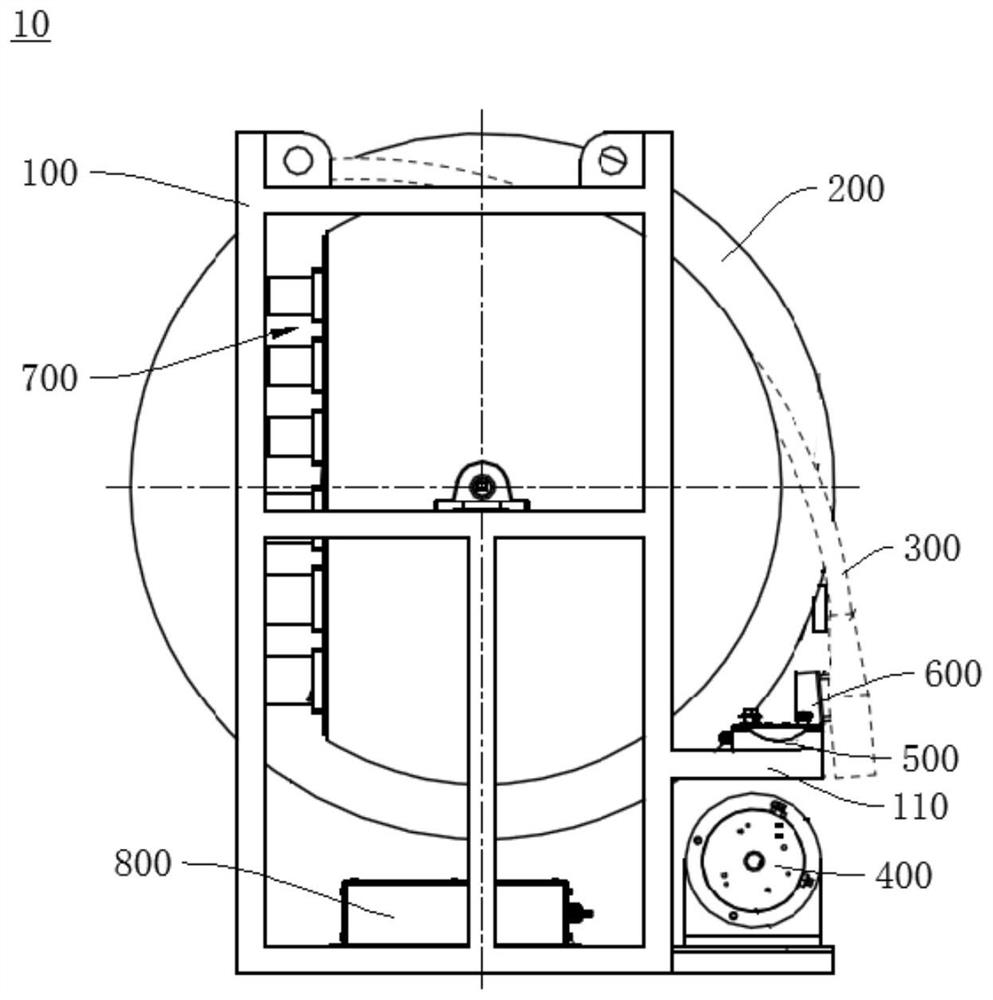
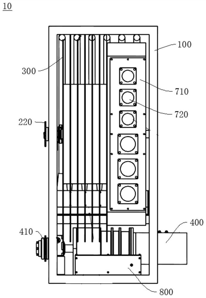
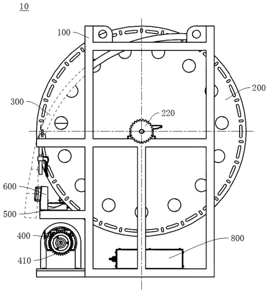
The invention provides a power output system, and relates to the technical field of power output equipment. The power output system comprises a frame body, a reel, a cable, a motor and a control device; the reel is rotatably connected to the frame body; the cable is wound on the reel and is configured to be wound or unwound in the rotating process of the reel; the motor is connected with the reel and is configured to drive the reel to rotate; and the control device is electrically connected with the motor, and the motor is configured to adjust the rotating speed according to a speed adjusting instruction sent by a user through the control device so as to adjust the rotating speed of the reel. The power output system provided by the invention can solve the problem that when traditional high-power power supply equipment is unfolded for work, personnel need to go back and forth a unit and a load end to connect the cable for many times, and the unfolding time is too long.

Description

technical field [0001] The present invention relates to the technical field of power output equipment, in particular to a power output system. Background technique [0002] Military field power supply equipment has higher and higher requirements for mobility, and the deployment time of the equipment is required to be as short as possible after it arrives at the position. When the equipment is deployed after arriving at the position, the most time-consuming part is the deployment of the cables. Especially for high-power power stations (above 1MW), there are even more than 100 connecting cables between the equipment. According to the traditional design, personnel have to go back and forth between the power station and the power equipment many times, and each time they can only drag 2 cables. The entire deployment time exceeds 30 minutes, which seriously affects the combat capability of the equipment. Contents of the invention [0003] The purpose of the present invention i...

Claims


Application Information

Patent Timeline
Patent Type & Authority Applications(China)
IPC IPC(8): B65H75/38B65H75/44
CPCB65H75/38B65H75/44B65H75/4486B65H75/4481B65H2701/34
Inventor 闵道广俞燕华范礼辉
Owner JIANGXI QINGHUA TAIHAO SANBO ELECTRICAL MACHINE
Why Eureka
Try Eureka