Pneumatic tire

A technology of pneumatic tires and tires, applied to tire parts, tire tread/tread pattern, vehicle parts, etc., can solve the problems of pull-out variation, damage, etc.

Active Publication Date: 2020-11-27
THE YOKOHAMA RUBBER CO LTD
View PDF18 Cites 0 Cited by
  • Summary
  • Abstract
  • Description
  • Claims
  • Application Information

AI Technical Summary

Problems solved by technology

However, in the wave-shaped sipe, the pull-out of the sipe blade provided in the mold during vulcanization molding is deteriorated, so that damage to the block is likely to occur when the sipe blade is pulled out from the tire.

Method used


Image

  • Pneumatic tire
  • Pneumatic tire
  • Pneumatic tire

Examples


Embodiment 3

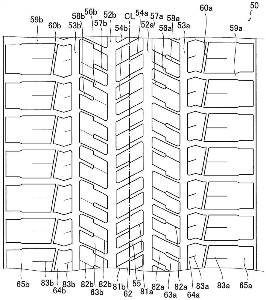
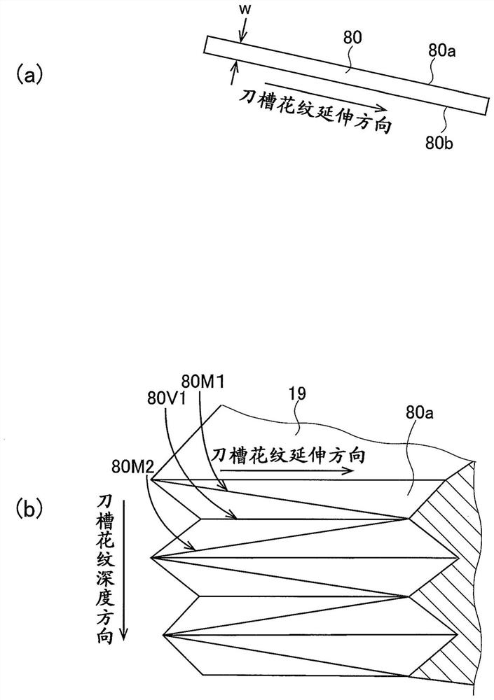
[0135] In Example 3, the sipes provided in the regions of the side land portions 64b, 65b are set so that the two opposing sipe wall surfaces are parallel and the sipe wall surfaces extend on a straight line in the sipe depth direction. For the flat sipe, the sipe provided in the region of the side land portions 64a and 65a in Example 6 is also set so that the two facing sipe wall surfaces are parallel and the sipe wall surface is at the depth of the sipe. A conventional sipe of a flat surface extending in a straight line in the direction.

[0136] [Table 1]

[0137]

[0138] [Table 2]

[0139]

[0140] It can be seen that all of Examples 1 to 6 have improved steering stability and high-speed durability compared with the conventional examples. From this, it can be seen that the rigidity against the falling deformation and the shearing deformation of the land portion provided with the sipe 80 can be appropriately imparted to the land portion.

[0141] From the comparis...


PUM


Abstract

Each pair of sipe wall surfaces of sipes provided to the tread section of a pneumatic tire comprises at least two peak sections and at least one valley section along the sipe depth direction, the peaksections and valley sections bending in a wave shape at positions in the sipe extension direction. When a sipe is viewed along the sipe depth direction, the recess depth of the valley section in relation to the peak section on one wall surface of the sipe varies in accordance with the position in the extension direction, the recess depth of the valley section extending from a maximum position toa minimum position, and the recess depth of the valley section decreasing moving from the deepest valley section toward the highest peak section. The sipes are provided in a first half tread region ona first side and / or a second half-tread region on a second side in the tire width direction.

Description

technical field [0001] The present invention relates to a pneumatic tire provided with a sipe on a tread portion. Background technique [0002] In general, in a pneumatic tire (hereinafter, simply referred to as a tire), a plurality of sipes extending in the tire width direction are provided in the blocks of the tread portion, and the edge effect and drainage effect of the sipes improve the wetness. Braking performance on roads and ice. However, if the sipe is provided, the rigidity of the block decreases, and therefore, when the block is new, an increase in wear and a decrease in steering stability on a dry road surface are caused by the block falling (Japanese: 头れ込み) or shear deformation. In addition, there is known a technique of increasing the rigidity of the block by suppressing deformation of the block by forming the sipe in a wave shape along the depth direction of the sipe. However, in the wave-shaped sipe, the pull-out of the sipe blade provided in the mold during...

Claims


Application Information

Patent Timeline
Patent Type & Authority Applications(China)
IPC IPC(8): B60C11/12B60C11/03
CPCB60C11/0306B60C11/0311B60C2011/0381B60C2011/1209B60C11/1218B60C11/1236B60C11/1259B60C11/11B60C11/1272B60C11/0304B60C11/12B60C2011/1213B60C2011/1227
Inventor 内田裕太
Owner THE YOKOHAMA RUBBER CO LTD
Why Eureka
Try Eureka