Pouring forming equipment for automatic production of transmission shell

A transmission housing and molding equipment technology, which is applied in the field of pouring and processing equipment, can solve the problems of limiting the efficiency of automatic production and processing, increasing the operational risk of staff, increasing the workload of operators, etc., and achieves strong safety and practicability. Simple, inexpensive to manufacture effect

Pending Publication Date: 2021-10-01
镇江市明辰压铸有限公司
View PDF8 Cites 0 Cited by
  • Summary
  • Abstract
  • Description
  • Claims
  • Application Information

AI Technical Summary

Problems solved by technology

[0003] As for transmission housing pouring and molding equipment, it is one of the equipment for transmission housing production. Most of the traditional pouring and molding processes require manual assistance, which limits production efficiency, increases the risk of staff operation, and is still insufficient in safety; and After the molten metal solution is poured into the mold cavity after the mold is closed, in order to avoid defects such as casting depressions caused by the air in the mold cavity, it is necessary to completely squeeze out the air during pouring until part of the pouring solution flows into the mold cavity, so as to ensure that the molten metal Liquid fills the mold cavity to ensure product quality, while the excess liquid that flows out stays in the flow channel. After working for a period of time, it is necessary to manually or mechanically take out the solidified material in the flow channel for recovery, which increases the workload of operators and limits automated production. The processing efficiency, so it is necessary to improve the design

Method used


Image

  • Pouring forming equipment for automatic production of transmission shell
  • Pouring forming equipment for automatic production of transmission shell
  • Pouring forming equipment for automatic production of transmission shell

Examples


Embodiment Construction

[0040] The following will clearly and completely describe the technical solutions in the embodiments of the present invention with reference to the accompanying drawings in the embodiments of the present invention. Obviously, the described embodiments are only some, not all, embodiments of the present invention. Based on the embodiments of the present invention, all other embodiments obtained by persons of ordinary skill in the art without making creative efforts belong to the protection scope of the present invention.

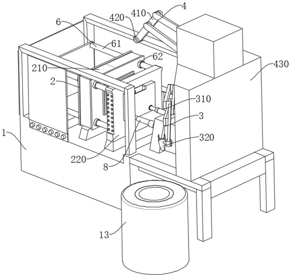
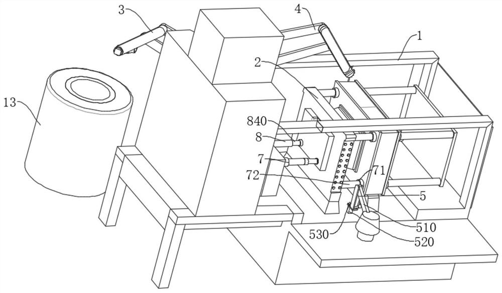
[0041] The present invention provides such Figure 1-4 The pouring and molding equipment for the automatic production of transmission housings is shown, including a pouring liquid storage tank 13, a mold clamping assembly 2 arranged on a frame 1, a pouring execution assembly 3, a mold cooling assembly 4, and a blanking mechanism 5;

[0042] The mold clamping assembly 2 includes a first mold clamping 210 which is slidably arranged on the frame 1 through the gui...


PUM


Abstract

The invention discloses pouring forming equipment for automatic production of a transmission shell. The pouring forming equipment comprises a pouring liquid storage tank, and a mold closing assembly, a pouring execution assembly, a mold cooling assembly and a discharging mechanism which are arranged on a rack, wherein the mold closing assembly comprises a first closing mold and a second closing mold, the first closing mold is arranged on the rack in a sliding manner through a guide mechanism, and the second closing mold is fixedly mounted on the rack and is relatively parallel to the first closing mold; the pouring execution assembly comprises a first mechanical arm unit rotatably arranged on the rack and a pouring cup rotatably mounted at the end of the first mechanical arm unit; the mold cooling assembly comprises a second mechanical arm unit rotatably arranged on the rack, an atomizing nozzle and a water tank; and the discharging mechanism comprises a third mechanical arm unit rotatably mounted on the rack, a first hydraulic oil cylinder and an electric clamping jaw. According to the equipment, automatic production of pouring processing can be achieved, the production efficiency is higher, the automation degree is high, the labor cost is reduced, and the safety and practicability are higher.

Description

technical field [0001] The invention belongs to the technical field of pouring processing equipment, and in particular relates to pouring molding equipment for automatic production of transmission housings. Background technique [0002] The transmission is a mechanism used to change the speed and torque from the engine. It can change the transmission ratio of the output shaft and the input shaft in fixed or stepwise steps, also known as the gearbox. Speed ​​changer is made up of speed change transmission mechanism and operating mechanism, and some automobiles also have power output mechanism. Most of the transmission mechanisms are driven by ordinary gears, and some are driven by planetary gears. Ordinary gear transmission transmission mechanisms generally use sliding gears and synchronizers, etc. With the rise of the automobile industry, the application of transmissions has also been expanded, and the transmission shell is an indispensable part of transmission parts, and i...

Claims


Application Information

Patent Timeline
Patent Type & Authority Applications(China)
IPC IPC(8): B29C39/02B29C39/22B29C39/26
CPCB29C39/02B29C39/26B29C39/22
Inventor 蔡明
Owner 镇江市明辰压铸有限公司
Why Eureka
Try Eureka