


Quick Research
Generate reliable direction feasibility study reports for your R&D in just a few steps.

Technical Q&A
Discover and master advanced knowledge NOW. Basics, ideas, possibilities, all at once.

Find Solutions
As an expert in R&D theories, this can generate solutions to your technical problems instantly.

Evaluate Feasibility
Analyze your overall solution with one click, know your potential R&D risks in advance.

Monitor Landscape
Get weekly tech updates, stay abreast of the latest tech innovations and key insights.
Auxiliary equipment for assembling electronic parts
A technology for electronic parts and auxiliary equipment, applied in the field of electronic parts assembly auxiliary equipment, can solve the problems of low wiring efficiency, mechanical equipment wiring, high hand strength requirements, etc., to reduce labor intensity, degree of automation and efficiency high effect
- Summary
- Abstract
- Description
- Claims
- Application Information
AI Technical Summary
Problems solved by technology
Method used
Image

Examples
Embodiment 1
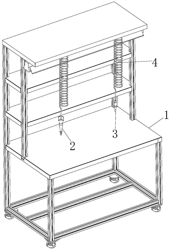
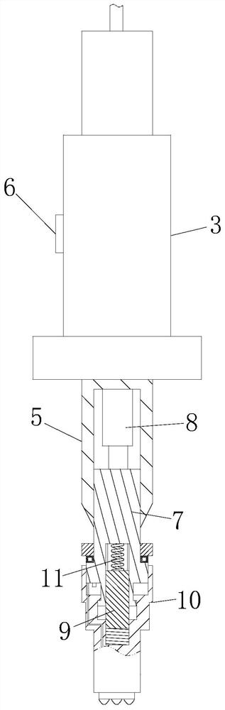
[0031] see Figure 1-7 As shown, an electronic component assembly auxiliary equipment includes a workbench 1, a screw gun 2 and a cable rod 3; the top of the fixed platform is connected with a first spring 4; the number of the first spring 4 is two, The bottom of one of the first springs 4 is fixedly connected with a screw gun 2, and the bottom of the other first spring 4 is fixedly connected with a cable rod 3; the cable rod 3 includes a rod body 5 and a control button 6 and the top 7; the side of the rod 5 is provided with a control button 6; the bottom surface of the rod 5 is provided with a chute; the inside of the chute is slidably connected with the top 7; the bottom of the chute is fixedly connected There is an electric ejector rod 8; when working, when assembling electronic parts and components, the standing tools screw gun 2, soldering equipment, and wiring rod 3, etc., are in a messy state during the assembly of electronic parts with lines. , in order to facilitate ...
Embodiment 2
[0041] see Figure 8 As shown, the bottom surface of the cleaning head 33 is provided with a threaded hole, and the threaded hole and the connecting hole are all connected to each other; the inside of the threaded hole is threaded to connect the thimble 35; Arranged thorns 36; during work, by threading the thimble 35 and the cleaning head 33, when the cleaning head 33 is exported under the action of air pressure, the gas will also be introduced into the threaded hole to promote the thimble inside the threaded hole. 35 is exported, and in the process that thimble 35 is exported, can synchronously rotate, coordinate the thorn block 36 that evenly arranges on the surface of thimble 35, can realize that the glue of fixed block 14 bottom surface dry state is cleaned and broken etc., is conducive to the shedding of glue.
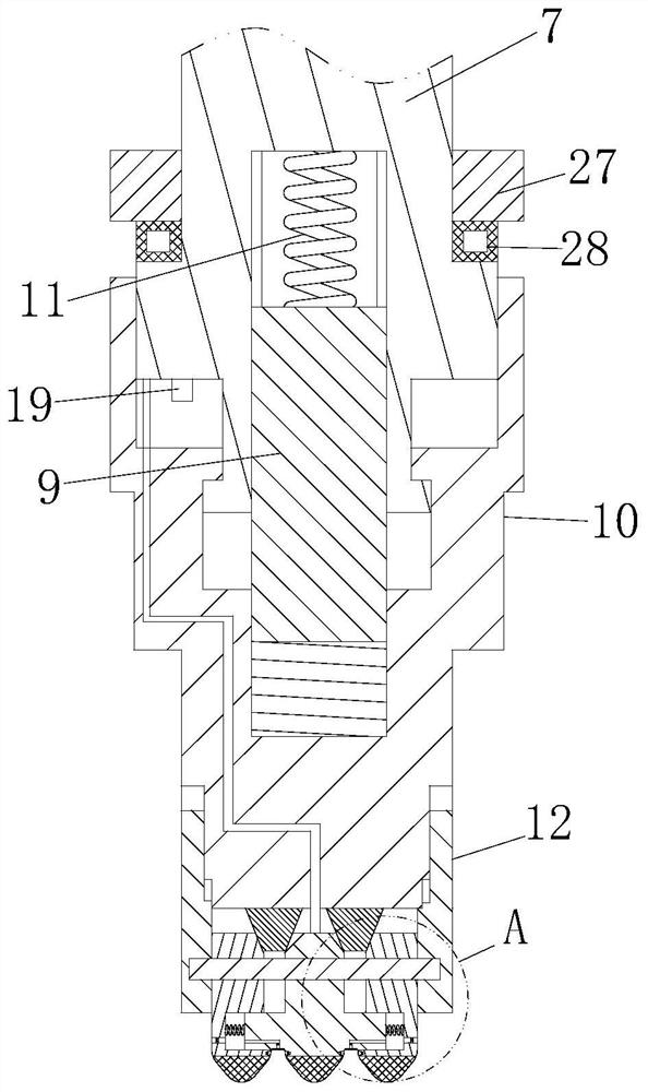
[0042]The working principle is that when the cable needs to be arranged, after the assembly is completed through the screw gun 2, the staff at the cable arrangeme...
PUM
 Abstract
Description
Claims
Application Information
 - R&D Engineer
- R&D Manager
- IP Professional
- Industry Leading Data Capabilities
- Powerful AI technology
- Patent DNA Extraction
Browse by: Latest US Patents, China's latest patents, Technical Efficacy Thesaurus, Application Domain, Technology Topic, Popular Technical Reports.
© 2024 PatSnap. All rights reserved.Legal|Privacy policy|Modern Slavery Act Transparency Statement|Sitemap|About US| Contact US: help@patsnap.com