Multi-line laser radar based on multiple lasers and detection method using multi-line laser radar

A multi-line laser and laser technology, used in radio wave measurement systems, instruments, measurement devices, etc., can solve problems such as inability to take into account high-level angular resolution and high scanning frequency, low reliability and stability, and waste of laser beams. , to facilitate communication, reduce the number and space occupied, and save costs

Active Publication Date: 2021-09-28
HESAI TECH CO LTD
View PDF8 Cites 0 Cited by
  • Summary
  • Abstract
  • Description
  • Claims
  • Application Information

AI Technical Summary

Problems solved by technology

This means that if the field of view is divided evenly up and down in the vertical direction, the laser beam emitted upwards is largely wasted
[0005] In addition, if all field of view angles are equally divided according to the angle division scheme of current market products, more lines are needed to achieve higher vertical resolution, which means higher cost, larger volume and lower reliability stability
Due to the limitation of the data capacity of the Ethernet and the processing speed of the on-board CPU, lidars with higher lines (such as Velodyne) cannot take into account high horizontal angular resolution and high scanning frequency at the same time
[0006] However, if the number of lines is reduced for the sake of cost reduction, then the angular interval is too large, and the target cannot be distinguished in a short distance range (such as 40 meters). rate), 16 lines are required, then the distance between the laser beams at a distance of 40m is about 1.4m, and it is easy to miss a pedestrian

Method used


Image

  • Multi-line laser radar based on multiple lasers and detection method using multi-line laser radar
  • Multi-line laser radar based on multiple lasers and detection method using multi-line laser radar
  • Multi-line laser radar based on multiple lasers and detection method using multi-line laser radar

Examples


Embodiment 1

[0027] A multi-line laser radar based on multiple lasers according to an embodiment of the present invention, the multi-line laser radar includes:

[0028] A rotor and a stator, the interior of the rotor is isolated as a firing cavity and a receiving cavity; the rotor and the stator are prior art in the art, and will not be repeated here;

[0029] figure 1 Schematically shows the structural diagram of the carrier and the laser in the embodiment of the present invention, as shown in figure 1 shown;

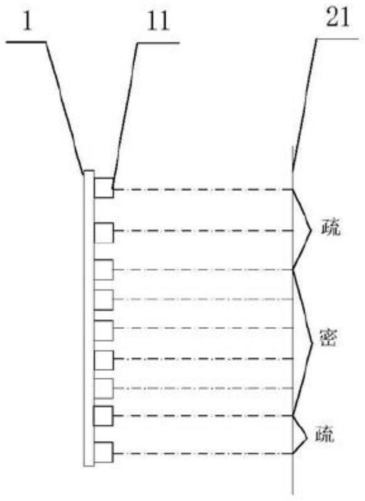
[0030] There is only one carrier 1 for carrying multiple lasers; the carrier is arranged in the emitting cavity;

[0031] A plurality of lasers 11, such as 20, 40, the specific number corresponds to the number of lines of the laser radar; the lasers are fixed on the carrier from top to bottom, and are collinear;

[0032] A light collimating device, such as a collimating lens, the projection point of the laser on the carrier on the vertical plane 21 including the main axis of the...

Embodiment 2

[0040] A multi-line laser radar based on multiple lasers in the embodiment of the present invention is different from Embodiment 1 in that:

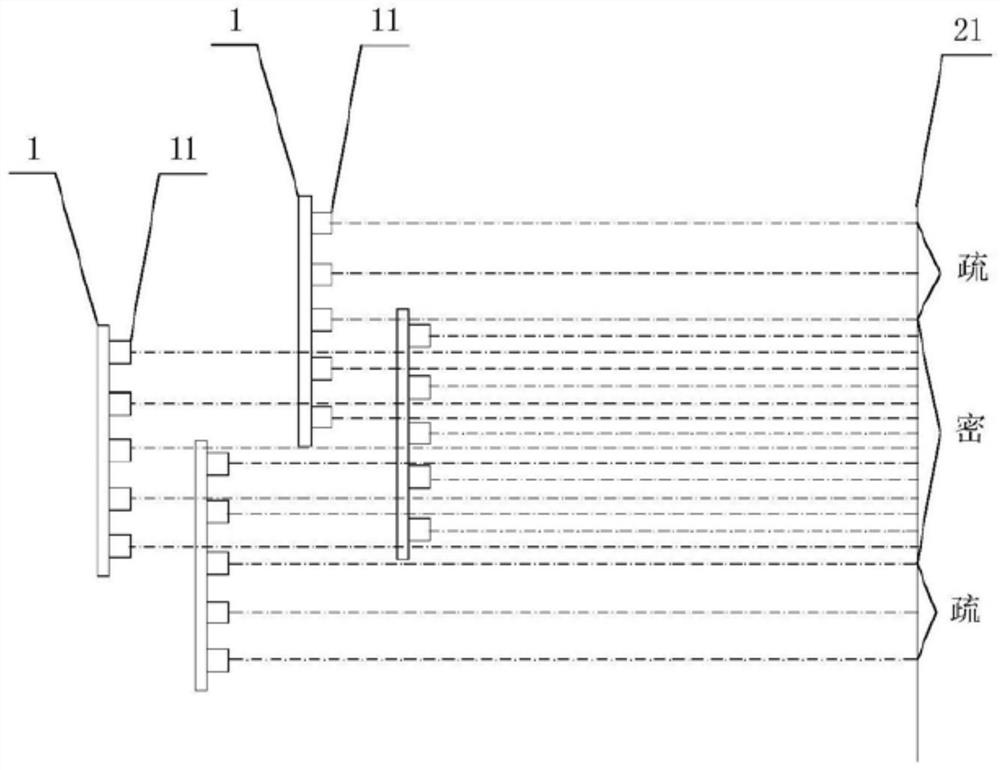
[0041] The plurality of lasers are not all collinear, such as most of the lasers are vertically arranged and collinear, with equal spacing, and a small number of lasers are vertically arranged and collinear, with equal intervals; the majority of the lasers and the small number of lasers are staggered in the horizontal direction, The projection points of the small part of the lasers on the vertical plane including the main axis of the optical collimation device are between the projection points of the majority of the lasers on the vertical plane, so that the projection points have a dense distribution, which improves the The beam density of the laser output beam in the horizontal direction and nearby, correspondingly improves the vertical angular resolution.

Embodiment 3

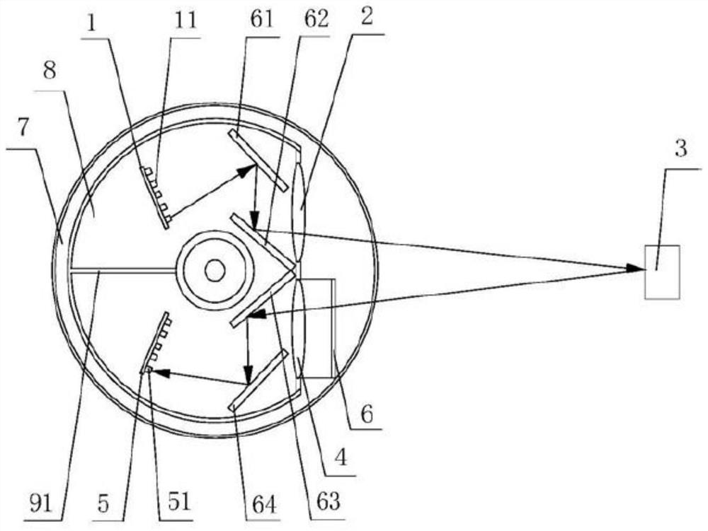
[0043] figure 2 A simplified structural diagram of a multi-line laser radar based on multiple lasers according to an embodiment of the present invention is schematically given, as shown in figure 2 As shown, the multi-line laser radar includes:

[0044] Rotor, stator, described rotor comprises inner cavity 8 and outer cavity 7, and the inside of described inner cavity 8 is isolated as launch cavity and receiving cavity, as isolating by dividing plate 91; Described rotor and stator are existing in the art Technology, no more details here;

[0045] The launch cavity is set:

[0046] image 3 A schematic diagram of the structure of the laser and the carrier of the embodiment of the present invention is given schematically, such as image 3 shown;

[0047] A plurality of carriers 1, such as 5, each carrier is vertically fixed in the emission cavity for carrying multiple lasers; a plurality of carriers 1 are distributed at intervals in the horizontal direction;

[0048] A p...


PUM


Abstract

The invention provides a multi-line laser radar based on multiple lasers, the multi-line laser radar comprises: a rotor, a stator and a middle shaft, wherein the multi-line laser radar further comprises a bearing body, the multiple lasers are arranged on the bearing body, and the bearing body is arranged in the rotor; and a light collimating device, a light receiving device and a photoelectric detector, wherein the light collimating device, the light receiving device and the photoelectric detector are arranged in the rotor; the multi-line laser radar is characterized in that after being reflected by an obstacle, detection light emitted by each laser device is converged on a corresponding photoelectric detector after passing through the light receiving device, and projection points of the laser devices on a vertical plane are distributed in a sparse and dense manner in the vertical direction; the wire harness of the multi-line laser radar is greater than or equal to 16. The method has the advantages of high vertical angle resolution, high horizontal angle resolution, high scanning frequency, more accurate scanning result and the like.

Description

[0001] This application is a divisional application of the invention patent application with the application number 201710463616.6 and the title of the invention "multi-line laser radar based on multiple lasers" filed on June 19, 2017. technical field [0002] The invention relates to laser radar, in particular to a multi-line laser radar based on multiple lasers and a detection method using it. Background technique [0003] In order to obtain as much 3D information of the scanned area as possible, multi-line lidar is currently used, which can cover more vertical field of view areas. At present, the beam angle distribution of multi-line laser radars on the market adopts the method of dividing evenly within a certain angle range (that is, the vertical angular resolution is a definite value), such as Velodyne's 16-line, 32-line and 64-line The angular resolutions are 2 degrees, 1.33 degrees and 0.43 degrees respectively, and the vertical angular resolution of Ibeo's 4-line and...

Claims


Application Information

Patent Timeline
Patent Type & Authority Applications(China)
IPC IPC(8): G01S7/481G01S17/931
CPCG01S17/931G01S7/481G01S7/4817Y02A90/10
Inventor 王瑞李娜向少卿李一帆
Owner HESAI TECH CO LTD
Why Eureka
Try Eureka