Full-automatic reed welding machine

A welding machine, fully automatic technology, applied in the direction of welding equipment, auxiliary welding equipment, welding/cutting auxiliary equipment, etc., can solve the problems of affecting production efficiency and increasing labor cost, so as to improve production efficiency, reduce labor cost, The effect of improving alignment accuracy

Active Publication Date: 2021-09-28
BULL GRP CO LTD +1
View PDF8 Cites 2 Cited by
  • Summary
  • Abstract
  • Description
  • Claims
  • Application Information

AI Technical Summary

Problems solved by technology

[0002]The conventional automatic welding machine cuts the reed structure and performs automatic welding in the automatic welding machine. This welding method has a disadvantage, that is, a separate The reed needs to be manually placed in the positioning mold for welding, and then the welding machine presses down to weld the silver wire segment on the reed to form a contact structure. In the above scheme, each worker needs to operate a welding machine independently, greatly It increases the labor cost of production and also affects the production efficiency. In order to solve the above technical problems, it is necessary to design a new automatic reed welding machine

Method used


Image

  • Full-automatic reed welding machine
  • Full-automatic reed welding machine
  • Full-automatic reed welding machine

Examples


Embodiment Construction

[0029] Below in conjunction with specific embodiment, further illustrate the present invention. It should be understood that these examples are only used to illustrate the present invention and are not intended to limit the scope of the present invention. In addition, it should be understood that after reading the teachings of the present invention, those skilled in the art can make various changes or modifications to the present invention, and these equivalent forms also fall within the scope defined by the appended claims of the present application.

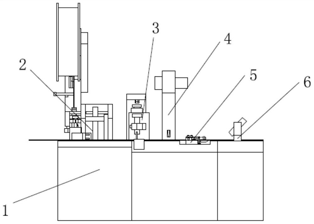
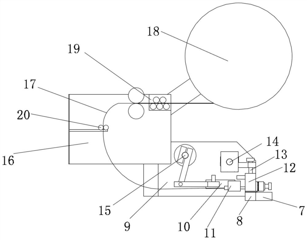
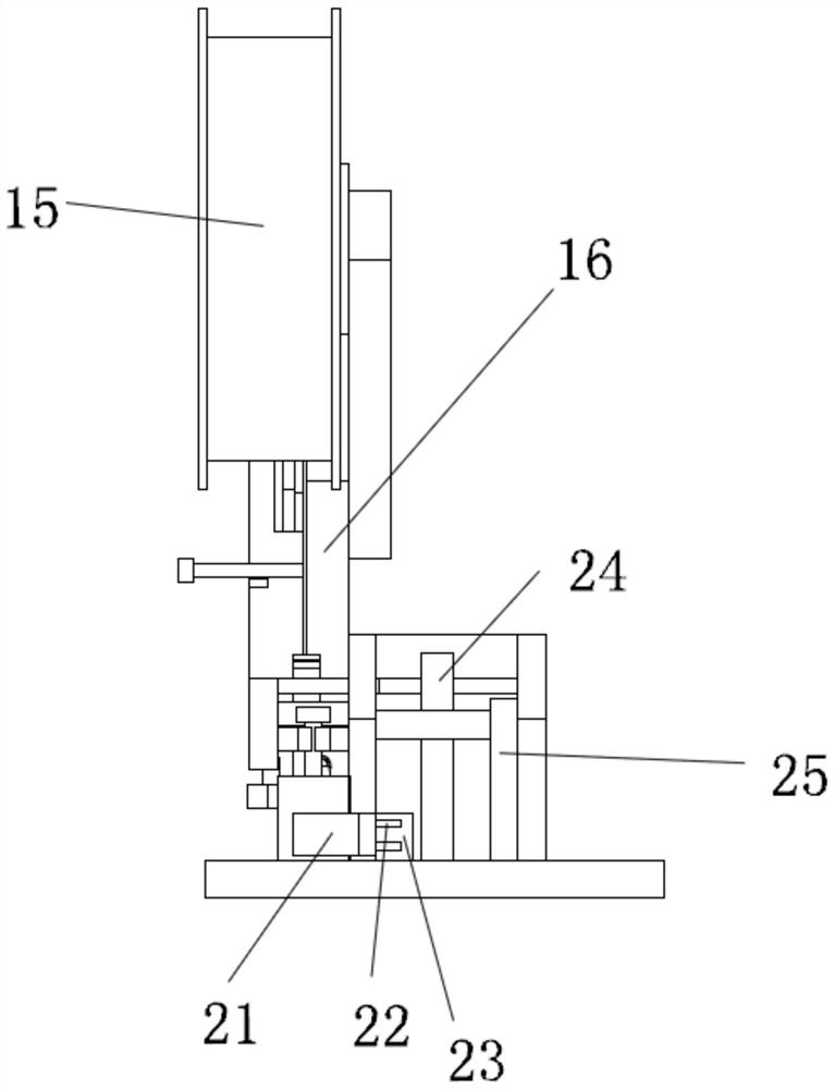
[0030] Embodiments of the present invention relate to a fully automatic reed welding machine, such as figure 1-shown in 3, including machine platform 1, reed transmission platform 7 and contact welding machine 2, described machine platform 1 upper end surface is installed with the reed transmission platform 7 for reed installation, described reed transmission platform 7 is equipped with contact welding machine 2, contact weldi...


PUM


Abstract

The invention relates to a full-automatic reed welding machine. The full-automatic reed welding machine comprises a machine table, a reed transmission platform and a contact welding machine, the reed transmission platform used for reed installation is installed on the upper end face of the machine table, the contact welding machine, a contact welding force detection machine, a contact trimming machine, a reed transmission machine and a detection structure are installed on the reed transmission platform from left to right, a silver wire transmission arm, a silver wire cutting-off base and a welding copper block are arranged in the contact welding machine, the silver wire transmission arm moves front and back, the front end of the silver wire transmission arm conveys a silver wire into the silver wire cutting-off base located on the reed transmission platform, the cut silver wire is welded into a reed structure in the reed transmission platform through the welding copper block with the rear portion moving downwards in an inclined mode, a shifting piece matched with a contact on the reed structure is arranged in the contact welding force detection machine, and a contact trimming rod capable of moving up and down is arranged on the contact trimming machine. The full-automatic reed welding machine has the characteristics of low energy consumption, stable reed transmission, high production efficiency, accurate positioning, improvement of product quality and the like.

Description

technical field [0001] The invention relates to the technical field of automatic reed welding, in particular to an automatic reed welding machine. Background technique [0002] Conventional automatic welding machines cut the reed structure and perform automatic welding in the automatic welding machine. This welding method has a disadvantage, that is, the individual reeds need to be manually placed in the positioning mold for welding. After that, the welding machine presses down to weld the silver wire segment on the reed to form a contact structure. In the above scheme, each worker needs to operate a welding machine independently, which greatly increases the labor cost of production and also affects production efficiency. In order to solve the above-mentioned technical problems, a new fully automatic reed welding machine needs to be designed. Contents of the invention [0003] The technical problem to be solved by the present invention is to provide a fully automatic reed...

Claims


Application Information

Patent Timeline
Patent Type & Authority Applications(China)
IPC IPC(8): B23K3/06B23K3/08B23K37/08G01N19/04
CPCB23K3/063B23K3/08B23K3/085B23K37/08G01N19/04
Inventor 章卫军陈兵张希伟史浙宏罗特苗祁文卓王小文
Owner BULL GRP CO LTD
Why Eureka
Try Eureka