


Quick Research
Generate reliable direction feasibility study reports for your R&D in just a few steps.

Technical Q&A
Discover and master advanced knowledge NOW. Basics, ideas, possibilities, all at once.

Find Solutions
As an expert in R&D theories, this can generate solutions to your technical problems instantly.

Evaluate Feasibility
Analyze your overall solution with one click, know your potential R&D risks in advance.

Monitor Landscape
Get weekly tech updates, stay abreast of the latest tech innovations and key insights.
Lawn garbage cleaning device
A garbage cleaning and lawn technology, which is applied to lawn growth, gardening, botany equipment and methods, etc., can solve the problem of large damage to the lawn, and achieve the effects of improving maintenance ability, convenient multi-channel maintenance, reducing cost and operating difficulty
- Summary
- Abstract
- Description
- Claims
- Application Information
AI Technical Summary
Problems solved by technology
Method used
Image

Examples
Embodiment 1
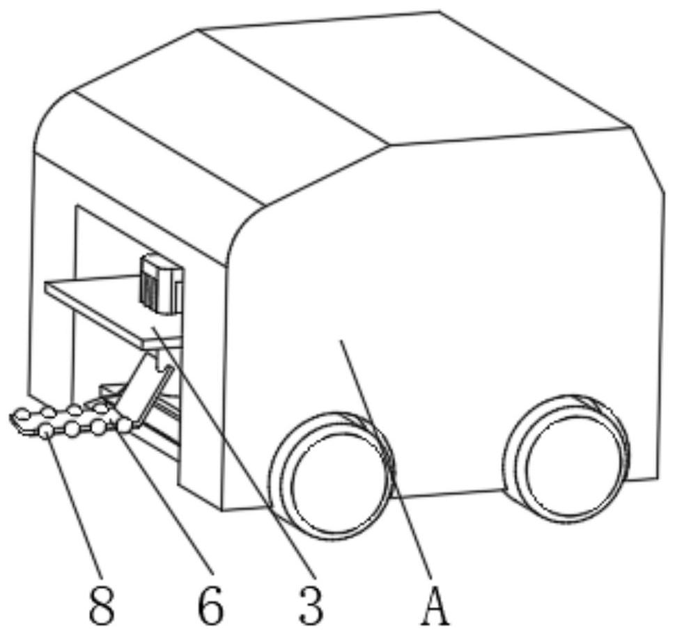
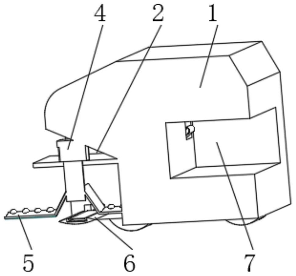
[0031] see Figure 1-2 , the present invention provides a technical solution: a lawn garbage cleaning device, including a fuselage 1, a cleaning tank 2 is provided on one side of the fuselage 1, a horizontal plate 3 is connected to one side of the inner wall of the cleaning tank 2, and the horizontal plate 3 The top is fixedly connected with a cleaning motor 4, and the output end of the cleaning motor 4 runs through the horizontal plate 3 and is symmetrically installed with a rotating plate 5. The inner wall of the cleaning tank 2 is located between the two sides of the inner wall and is fixedly connected with a conveying plate 6 under the rotating plate 5. 1 There is a storage tank 7 on the side away from the cleaning tank 2, the storage tank 7 extends to a position close to the cleaning motor 4, both ends of the conveying plate 6 run through the fuselage 1 and extend to the inside of the storage tank 7, the rotating plate 5 The outside is evenly equipped with guide balls 8. ...
Embodiment 2
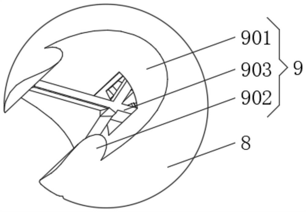
[0035] see Figure 1-4 , the present invention provides a technical solution: on the basis of Embodiment 1, a trimming device 9 is installed on the side of the guide ball 8 away from the rotating plate 5, the trimming device 9 includes a trimming groove 901, and the inner wall of the trimming groove 901 is far away from the rotating plate 5 One end of is symmetrically equipped with protective column 902, and the inside of trimming groove 901 is rotationally connected with trimming knife 903, and one side of the inner wall of trimming groove 901 is fixedly connected with trimming knife 903 by back-moving spring 904.
[0036] The inner bottom of the trimming groove 901 is provided with a drive groove 12, the drive groove 12 runs through the guide ball 8, and the drive wheel 13 is connected to the inner wall of the drive groove 12. The width of the drive wheel 13 gradually decreases from top to bottom. The outside of the wheel 13 is uniformly equipped with anti-skid bumps 14, and...
Embodiment 3
[0040] see Figure 1-7 , the present invention provides a kind of technical scheme: on the basis of embodiment one, the bottom of rotating plate 5 and conveying plate 6 all offers carding groove 10, and the inside of carding groove 10 is equipped with carding device 11, and carding device 11 comprises carding column 111, the carding column 111 is driven by an external drive motor, and the outside of the carding column 111 is evenly provided with an opening and closing groove 112, and one side of the inner wall of the opening and closing groove 112 is rotated and connected with a carding rod 113, and one side of the inner wall of the opening and closing groove 112 passes through The elastic plate 114 is fixedly connected with the combing rod 113 .
[0041] The interior of the carding column 111 is uniformly provided with inclined grooves 16 , the inclined grooves 16 communicate with the opening and closing grooves 112 , and the insides of the inclined grooves 16 are filled with m...
PUM
 Abstract
Description
Claims
Application Information
 - R&D Engineer
- R&D Manager
- IP Professional
- Industry Leading Data Capabilities
- Powerful AI technology
- Patent DNA Extraction
Browse by: Latest US Patents, China's latest patents, Technical Efficacy Thesaurus, Application Domain, Technology Topic, Popular Technical Reports.
© 2024 PatSnap. All rights reserved.Legal|Privacy policy|Modern Slavery Act Transparency Statement|Sitemap|About US| Contact US: help@patsnap.com