Video coding method, system and storage medium
A video encoding and encoding technology, which is applied in digital video signal modification, image communication, electrical components, etc., can solve problems such as inability to guarantee inter-frame compression performance, achieve the effect of reducing encoding time and improving encoding performance
- Summary
- Abstract
- Description
- Claims
- Application Information
AI Technical Summary
Problems solved by technology
Method used
Image
Examples
Embodiment 1
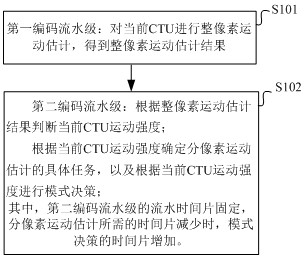
[0065] figure 1 A flow chart of steps of a video coding method according to an embodiment of the present application is shown in FIG.
[0066] Such as figure 1 As shown, the video encoding method of this embodiment specifically includes the following steps:
[0067] S101: the first encoding pipeline stage: performing integer pixel motion estimation on the current CTU to obtain an integer pixel motion estimation result.
[0068] S102: The second encoding pipeline stage: judge the current CTU motion intensity according to the whole pixel motion estimation result; determine the specific task of sub-pixel motion estimation according to the current CTU motion intensity, and make mode decision according to the current CTU motion intensity;
[0069] Wherein, the pipeline time slice of the second encoding pipeline stage is fixed, and when the time slice required for sub-pixel motion estimation decreases, the time slice for mode decision increases.
[0070] Specifically, refer to ...
Embodiment 2
[0123] This embodiment provides a video encoding system. For details not disclosed in the video encoding system of this embodiment, please refer to the specific implementation content of the video encoding method in other embodiments.
[0124] Figure 5A schematic structural diagram of a video encoding system according to an embodiment of the present application is shown.
[0125] Such as Figure 5 As shown, a video encoding system provided in this embodiment specifically includes a first encoding pipeline stage module 10 and a second encoding pipeline stage module 20 .
[0126] specific,
[0127] The first encoding pipeline stage module 10: used for performing integer pixel motion estimation on the current CTU to obtain an integer pixel motion estimation result.
[0128] The second encoding pipeline level module 20: used to judge the current CTU motion intensity according to the whole pixel motion estimation result; and used to determine the specific task of sub-pixel moti...
Embodiment 3
[0150] This embodiment provides a video encoding device. For details not disclosed in the video encoding device of this embodiment, please refer to the specific implementation content of the video encoding method or system in other embodiments.
[0151] Figure 6 A schematic structural diagram of a video encoding device 400 according to an embodiment of the present application is shown in .
[0152] Such as Figure 6 As shown, the video encoding device 400 includes:
[0153] Memory 402: for storing executable instructions; and
[0154] Processor 401: used to connect with memory 402 to execute executable instructions so as to complete the motion vector prediction method.
[0155] Those skilled in the art can understand that the Figure 6 It is only an example of the video encoding device 400, and does not constitute a limitation to the video encoding device 400. It may include more or fewer components than shown in the figure, or combine certain components, or different com...
PUM
 Abstract
Description
Claims
Application Information
 - R&D
- Intellectual Property
- Life Sciences
- Materials
- Tech Scout
- Unparalleled Data Quality
- Higher Quality Content
- 60% Fewer Hallucinations
Browse by: Latest US Patents, China's latest patents, Technical Efficacy Thesaurus, Application Domain, Technology Topic, Popular Technical Reports.
© 2025 PatSnap. All rights reserved.Legal|Privacy policy|Modern Slavery Act Transparency Statement|Sitemap|About US| Contact US: help@patsnap.com


