A voltage-controlled emitter turn-off thyristor device and its manufacturing method

A thyristor and emitter technology, which is used in semiconductor/solid-state device manufacturing, thyristor, semiconductor devices, etc., can solve the problems of complex control when the device is turned on and off, difficult to meet the requirements of converter control technology, and slow dynamic response.

Active Publication Date: 2022-04-08
UNIV OF ELECTRONICS SCI & TECH OF CHINA
View PDF11 Cites 0 Cited by
  • Summary
  • Abstract
  • Description
  • Claims
  • Application Information

AI Technical Summary

Problems solved by technology

[0003] In megawatt-level power applications, the thyristor used to be the only application device, but because it is a semi-controlled device, it has no gate turn-off capability, and it is difficult to meet the requirements of modern converter control technology.
GTO has been successful in high voltage direct current transmission (HVDC) and megawatt-level applications, but the disadvantages are: the uneven distribution of the turn-on transient current will cause di / dt problems, requiring di / dt buffers; it also causes reverse bias The safe operating area (RBSOA) is relatively small; the p-n-p-n four-layer structure makes GTO more sensitive to dv / dt, so a dv / dt buffer is required when shutting down; the gate driver is bulky and consumes hundreds of watts of power; the storage time is long , the dynamic response is slow, and the working frequency is generally limited below 1kHz
[0005] However, since the emitter turn-off thyristor (ETO) has three gates, the control of device turn-on and turn-off is complicated
Although the ETO device only needs to control the gate voltage when it is turned off, it needs to inject a strong current trigger pulse into the gate of the GTO when the ETO is turned on, so its driving circuit is complicated and it is not conducive to improving the reliability of the system.

Method used


Image

  • A voltage-controlled emitter turn-off thyristor device and its manufacturing method
  • A voltage-controlled emitter turn-off thyristor device and its manufacturing method
  • A voltage-controlled emitter turn-off thyristor device and its manufacturing method

Examples


Embodiment Construction

[0039] Below in conjunction with accompanying drawing and embodiment, describe technical solution of the present invention in detail:

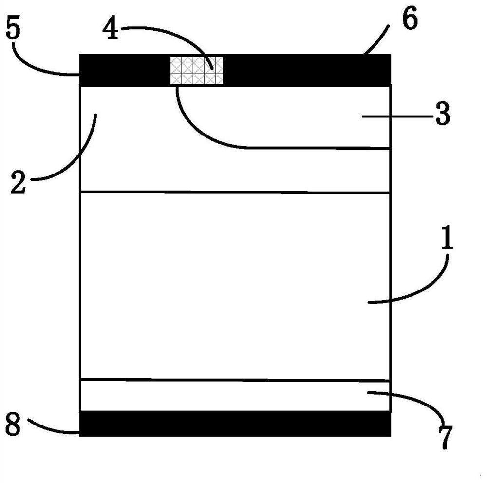
[0040] figure 1 It is a schematic diagram of the structure of a conventional GTO device.

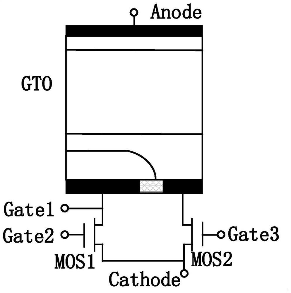
[0041] figure 2 It is a schematic structural diagram of an ETO device composed of a conventional GTO and two MOSs. It has a parasitic thyristor structure, which has a large di / dt when it is turned on, and a small conduction voltage drop when it is turned on. However, since the emitter turn-off thyristor (ETO) has three gates, the control when the device is turned on and off is complicated. Although the ETO device only needs to control the gate voltage when it is turned off, it needs to inject a strong current trigger pulse into the GTO gate when the ETO is turned on, so its driving circuit is complicated and it is not conducive to improving the reliability of the system.

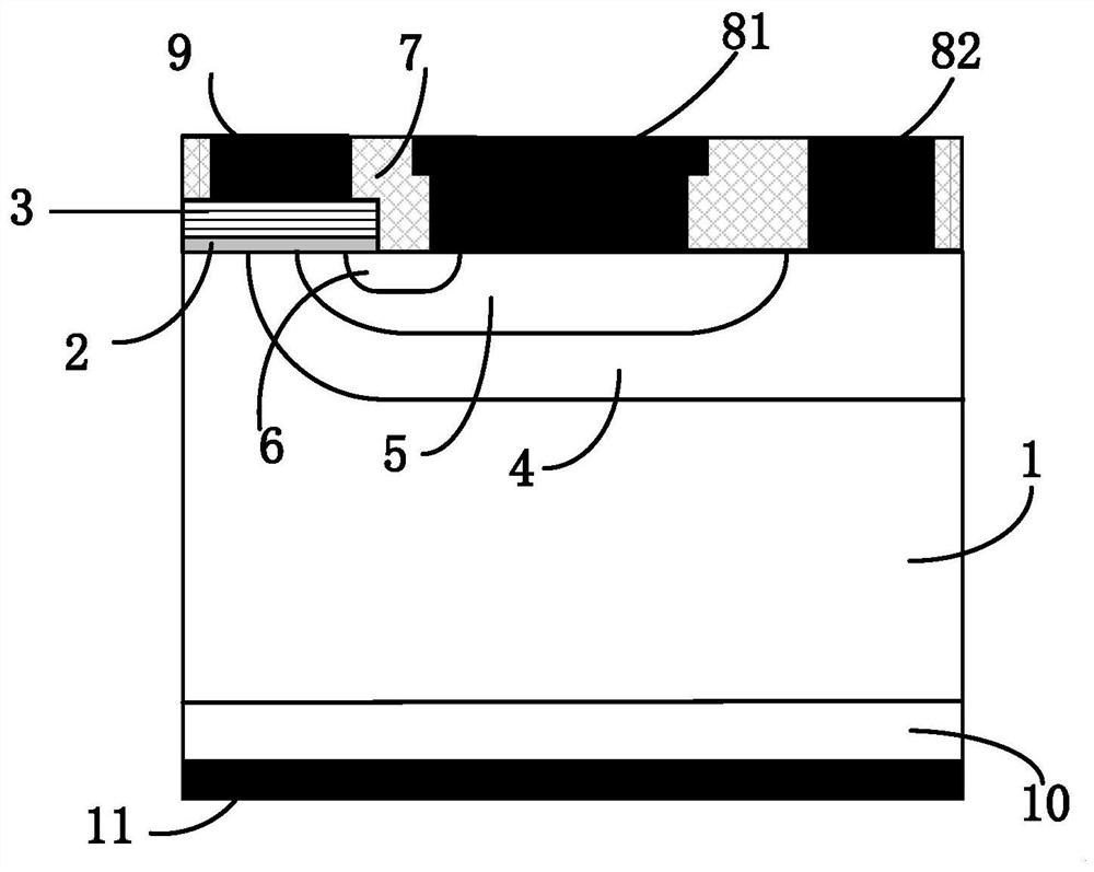
[0042] image 3 It is a structural schematic diagram of a MOS gate-controlled...


PUM


Abstract

The invention belongs to the technical field of power semiconductors, and in particular relates to a voltage-controlled emitter turn-off thyristor and a manufacturing method thereof. The present invention realizes the turn-on and turn-off of the device completely controlled by the voltage of a single gate by designing a double-cathode MCT device structure and externally connecting NMOS and diodes. Therefore, the structure of the present invention avoids the fact that the emitter turn-off thyristor (ETO) has three gates, which causes complicated control when the device is turned on and off, and needs to inject a strong current trigger pulse into the GTO gate when the ETO is turned on, resulting in Its driving circuit is complex and bulky.

Description

technical field [0001] The invention belongs to the technical field of power semiconductors, and in particular relates to a voltage-controlled emitter turn-off thyristor and a manufacturing method thereof. Background technique [0002] The development of renewable energy such as solar energy and wind energy is an important way to reduce carbon emissions. Renewable energy facilities convert electrical energy into conventional 60Hz AC power that meets the needs of users and industries through power electronic converters. Due to the relatively large power levels involved, the power semiconductors used in the above application fields must have the ability to handle high voltage and high current. [0003] In megawatt power applications, the thyristor used to be the only application device, but because it is a semi-controlled device, it has no gate turn-off capability, and it is difficult to meet the requirements of modern converter control technology. GTO has been successful in...

Claims


Application Information

Patent Timeline
Patent Type & Authority Patents(China)
IPC IPC(8): H01L29/06H01L29/74H01L21/332
CPCH01L29/74H01L29/7424H01L29/0603H01L29/0684H01L29/66363
Inventor 陈万军朱建泽汪淳朋杨超刘超
Owner UNIV OF ELECTRONICS SCI & TECH OF CHINA
Why Eureka
Try Eureka