Dispensing equipment for lamp production

A technology for dispensing and lighting, which is applied to coatings, devices that apply liquid to the surface, etc., which can solve the problems of the lamp holder not being fixed and sealed, the uneven dispensing of the lamp holder, and the unqualified products.

Active Publication Date: 2021-09-24
中山市莱利灯饰股份有限公司
View PDF7 Cites 1 Cited by
  • Summary
  • Abstract
  • Description
  • Claims
  • Application Information

AI Technical Summary

Problems solved by technology

[0005] The purpose of the present invention is to provide a dispensing equipment for lamp production to solve the problem that the existing dispensing equipment can only limit the position by friction after the lamp holder is placed on the placement seat. However, the surface of the lamp holder is generally It is relatively smooth, and the lamp holder is prone to slipping relative to the placement seat, causing the placement seat to rotate a circle, but the lamp holder does not rotate a circle, so that the lamp holder is not evenly glued, and the position where the lamp holder is not glued is also not. Get fixed and sealed, resulting in non-conforming product issues

Method used


Image

  • Dispensing equipment for lamp production
  • Dispensing equipment for lamp production
  • Dispensing equipment for lamp production

Examples


Embodiment Construction

[0038] In order to enable those skilled in the art to better understand the present invention, the technical solution of the present invention will be further described below in conjunction with the accompanying drawings and embodiments.

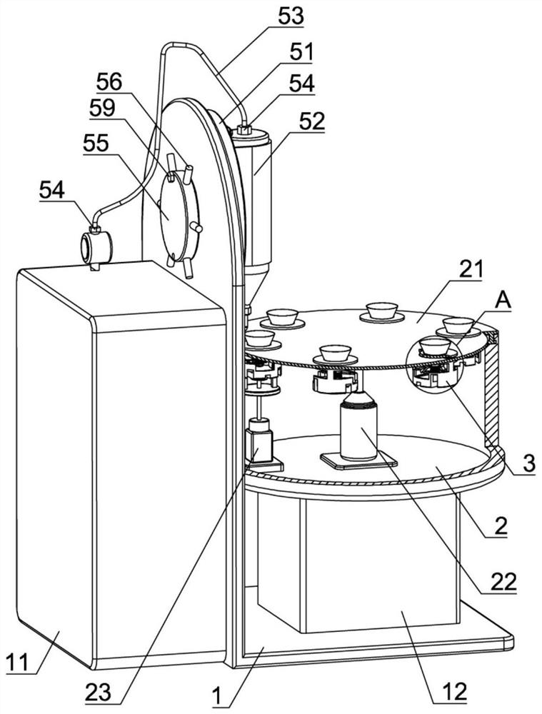
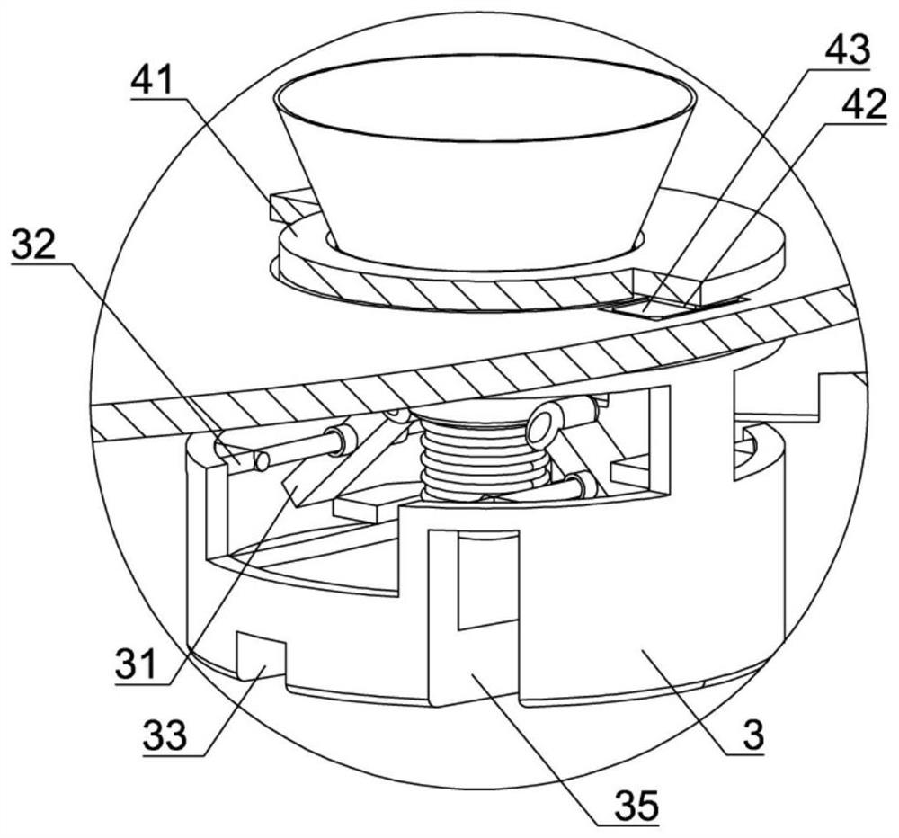
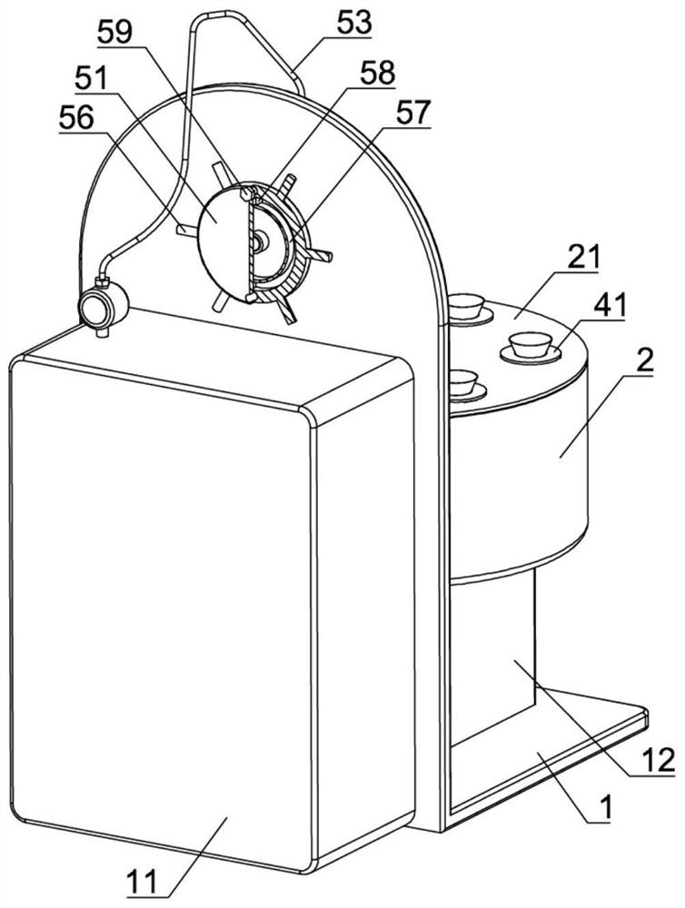
[0039] Such as Figure 1-Figure 9 As shown, a dispensing equipment for lamp production of the present invention includes an L-shaped frame 1, a first electric control box 11 is installed on one side of the L-shaped frame 1, and a second electric control box 11 is installed on the bottom of the L-shaped frame 1. Box 12, L-shaped frame 1 is also equipped with a dispensing mechanism, the first electric control box 11 is electrically connected with the dispensing mechanism; the second electric control box 12 upper side is fixedly connected with a workbench 2, and the workbench 2 includes a round Shaped turntable 21, the first stepper motor 22, the second stepper motor 23 and the lamp holder placement mechanism, the circular turntable 21 is conne...


PUM


Abstract

The invention belongs to the technical field of lamp processing, and particularly relates to dispensing equipment for lamp production. The dispensing equipment comprises an L-shaped rack, wherein the L-shaped rack is provided with a first electric control box, a second electric control box and a dispensing mechanism; the second electric control box is connected with a workbench; the workbench comprises a circular rotary table, a first step motor, a second step motor and a lamp holder placing mechanism; the lamp holder placing mechanism comprises a circular placing base; the circular placing base is provided with a clamping plate; a second circular-arc slot and a third circular-arc slot are formed in the circular placing base; the output shaft of the second step motor is connected with a second rotary disc; the second rotary disc is provided with an elastic telescopic ejector rod; and the second circular-arc slot and the third circular-arc slot are connected with supporting plates. By the dispensing equipment, the problems that existing dispensing equipment only can limit a lamp holder through friction force after the lamp holder is placed on the placing base, so that the lamp holder is likely to slip relative to the placing base, and therefore, dispensing of the lamp holder is not uniform; and meanwhile, the non-glued position of the lamp holder part is not fixed and sealed, so that the product is unqualified are solved.

Description

technical field [0001] The invention belongs to the technical field of lamp processing, and in particular relates to a glue dispensing device for lamp production. Background technique [0002] LED lights are one of the most commonly used electrical products in people's lives. LED lights are usually composed of lamp holders, PCB circuit boards, lamp beads, lamp holders and lampshades. The lamp beads are fixed on the PCB circuit board by soldering. During the process, the workers usually put the PCB circuit board and the lamp beads inside the lamp holder first, then lead out the connecting wires on the PCB circuit board, connect the connecting wires to the lamp holder by riveting the metal lamp holder, and then place the wires on the lamp holder after the above processing. The semi-finished products are dispensed glue on the lamp holder by dispensing equipment, and finally buckle the bubble, buckle the lampshade on the lamp holder, and seal and fix it with glue. [0003] The ...

Claims


Application Information

Patent Timeline
Patent Type & Authority Applications(China)
IPC IPC(8): B05C5/02B05C13/02
CPCB05C5/0212B05C13/02
Inventor 黄官明安金波韦礼杰王斌
Owner 中山市莱利灯饰股份有限公司
Why Eureka
Try Eureka