
Flue gas distributor device with automatic ash removal function

An automatic dust removal and distributor technology, applied in the field of environmental engineering, can solve the problems of increasing the flue gas flow rate, poor flue gas diffusion effect, no explanation or report found, etc., to achieve the effect of preventing blockage, good effect, and preventing flow loss

Pending Publication Date: 2021-09-24
上海麦雀斯环境工程技术有限公司 +1
View PDF1 Cites 2 Cited by
  • Summary
  • Abstract
  • Description
  • Claims
  • Application Information

AI Technical Summary

Problems solved by technology

[0005] 1) This absorption tower is designed for wet desulfurization. The liquid droplets sprayed from the upper nozzle in the tower and the flue gas entering from the lower part of the tower are mixed to produce desulfurization effect, rather than the SDA semi-dry desulfurization system design. The structure and principle cannot be applied Semi-dry desulfurization project;
[0006] 2) This absorption tower does not increase the flue gas flow rate during the smoke intake process, and then diffuses evenly to the entire tower body, and the flue gas diffusion effect is poor;
[0007] 3) The deflector of this absorption tower is relatively simple, but the flue gas is guided to the liquid by the deflector 1 first, and then the flue gas is concentrated in the middle by the deflector 2, and the flue gas diffusion effect is poor;
[0008] 4) This absorption tower cannot realize the function of automatic dust removal and anti-blocking
[0009] At present, there is no description or report of the similar technology of the present invention, and no similar data at home and abroad have been collected yet.

Method used


Image

  • Flue gas distributor device with automatic ash removal function
  • Flue gas distributor device with automatic ash removal function
  • Flue gas distributor device with automatic ash removal function

Examples


Embodiment Construction

[0045] The following is a detailed description of the embodiments of the present invention: this embodiment is implemented on the premise of the technical solution of the present invention, and provides detailed implementation methods and specific operation processes. It should be noted that those skilled in the art can make several modifications and improvements without departing from the concept of the present invention, and these all belong to the protection scope of the present invention.

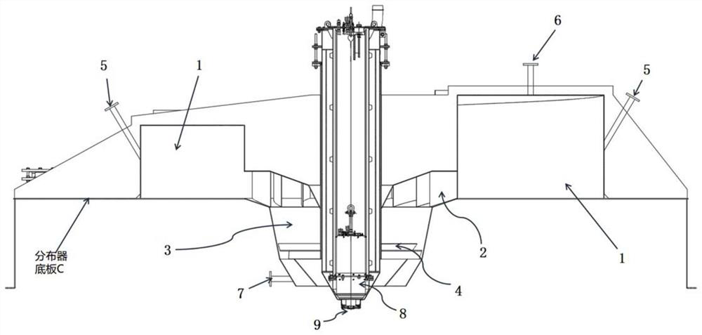
[0046] figure 1 It is a schematic structural diagram of a smoke distributor device with an automatic dust cleaning function provided by an embodiment of the present invention.

[0047] Such as figure 1 As shown, the smoke distributor device with automatic dust removal function provided by this embodiment may include: a smoke inlet flue 1, a first layer of guide vanes 2 arranged inside the smoke inlet flue 1, and a first layer of The flue gas vertical channel 3 connected to the outlet ...


PUM


Abstract

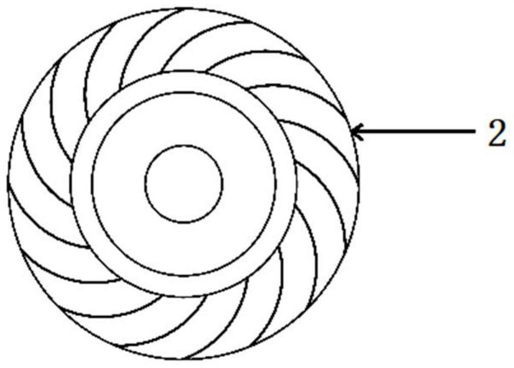
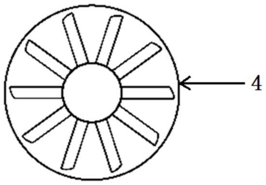
The invention provides a flue gas distributor device with an automatic ash removal function. The flue gas distributor device comprises a flue gas inlet flue, a first layer of guide vanes arranged on the inner side of the flue gas inlet flue, a flue gas vertical channel connected with the outlet end of the first layer of guide vanes, and a second layer of guide vanes connected with the outlet end of the flue gas vertical channel., The smoke inlet flue rotates towards the center in the anticlockwise direction in the form of an Archimedes spiral and is folded, so that the flow rate of smoke is increased. The first layer of guide vanes comprises a plurality of flue guide vanes which are uniformly distributed on the inner side of the smoke inlet flue, and uniformly converges smoke into the smoke vertical channel anticlockwise. The second layer of guide vanes comprises a plurality of smoke outlet guide vanes, an angle is formed between the guide vanes at the smoke outlet end and the horizontal direction, and the second layer of guide vanes evenly diffuses smoke in an anticlockwise umbrella-shaped mode. Smoke is evenly distributed through the multiple stages of guide vanes, meanwhile, ash can be automatically removed according to the pressure value, and smoke blockage and flow loss are prevented.

Description

technical field [0001] The invention relates to a flue gas treatment technology in the technical field of environmental engineering, in particular to a flue gas distributor device with an automatic dust cleaning function. Background technique [0002] The existing flue gas distributor is mainly used for flue gas treatment, for example, it can be used in semi-dry desulfurization equipment. The flue gas distributor guides the flue gas entering from the distributor inlet to distribute the flue gas, but due to the lack of a suitable diversion design, it is often impossible to distribute the flue gas evenly. If the flue gas cannot be evenly distributed, the subsequent process process, cannot achieve good results. Moreover, with the accumulation of usage time in the process, ash accumulation will gradually form in the flue gas channel of the flue gas distributor, which cannot be discharged with the flue gas. When the amount of ash accumulation reaches a certain level, it will aff...

Claims


Application Information

Patent Timeline
IPC IPC(8): B01D53/80B01D53/48B01D45/18
CPCB01D53/80B01D53/48B01D45/18B01D2258/0283
Inventor 施剑
Owner 上海麦雀斯环境工程技术有限公司
Learn More