Gyroscope
A gyroscope and resonator technology, applied in the field of gyroscopes, can solve problems such as insufficient drive/detection sensitivity, and achieve the effect of improving drive/detection sensitivity
- Summary
- Abstract
- Description
- Claims
- Application Information
AI Technical Summary
Problems solved by technology
Method used
Image
Examples
Embodiment 1
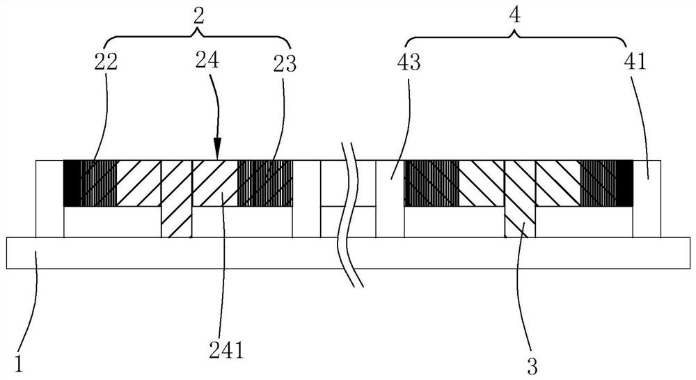
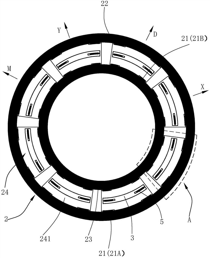
[0039] Please refer to Figure 1 to Figure 3 , the gyroscope 100 includes a base 1 , a resonator 2 suspended on the base 1 , and an anchor point 3 and an electrode assembly 4 fixed on the base 1 .
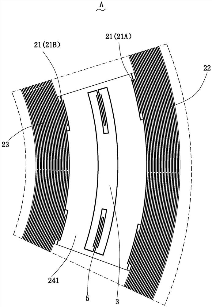
[0040] The resonator 2 includes a resonant beam 21 and an outer resonator 22, an inner resonator 23, and a middle resonator 24 all in the shape of a ring, and the middle resonator 24 is sleeved on the outside of the inner resonator 23, so that The outer resonator 22 is sleeved on the outer side of the middle resonator 24 .
[0041] The middle resonator 24 includes 8N resonant units 241 uniformly distributed along the circumferential direction of the inner resonator 23, and the resonant beam 21 is divided into a first resonant unit connecting the resonant unit 241 and the outer resonator 22. The beam 21A and the second resonant beam 21B connecting the inner resonator 23 and the resonant unit 241 . Wherein, N is a positive integer, and the resonant beam 21 can be elastically deform...
Embodiment 2
[0053] Please refer to Figure 4 to Figure 6 The difference between the second embodiment and the first embodiment is only that: when the moving direction of the middle resonator 24 is designed to be consistent with that of the outer resonator 22 and the inner resonator 23, the electrode assembly 4' includes the second An electrode 41' and a second electrode 43', the first electrode 41' and the second electrode 43' are respectively arranged on opposite sides of the anchor point 3 along the radial direction of the inner resonator 23, wherein , the resonant unit 241 is formed with a first comb-tooth portion 24C, the first electrode 41 ′ and the second electrode 43 ′ are both formed with a second comb-tooth portion 24D, and the first comb-tooth portion 24C The comb teeth of the comb teeth and the comb teeth of the second comb tooth part 24D are interleaved and interleaved and spaced from each other to form a capacitor. Therefore, variable area combs can be used to realize the el...
Embodiment 3
[0055] see Figure 7 with Figure 8 , the difference between the third embodiment and the first embodiment is only:
[0056] A decoupling structure 6 arranged around the anchor point 3 is provided between the anchor point 3 and the resonance unit 241 .
[0057] The decoupling structure 6 includes a first part 61 and a second part 63, the first part 61 is provided on two opposite sides of the anchor point 3 along the circumferential direction of the resonance unit 241, and the anchor point 3 is arranged along the Two opposite sides in the radial direction of the resonant unit 241 are provided with the second part 63, the first coupling beam 5A is connected between the first part 61 and the anchor point 3, and the second part 63 and the resonance unit 241 is connected with a second coupling beam 5B, wherein the first coupling beam 5A can only be elastically deformed in the radial direction of the inner resonator 23, and the second The coupling beam 5B is elastically deformabl...
PUM
 Abstract
Description
Claims
Application Information
 - Generate Ideas
- Intellectual Property
- Life Sciences
- Materials
- Tech Scout
- Unparalleled Data Quality
- Higher Quality Content
- 60% Fewer Hallucinations
Browse by: Latest US Patents, China's latest patents, Technical Efficacy Thesaurus, Application Domain, Technology Topic, Popular Technical Reports.
© 2025 PatSnap. All rights reserved.Legal|Privacy policy|Modern Slavery Act Transparency Statement|Sitemap|About US| Contact US: help@patsnap.com


