Non-inductive brushless permanent magnet motor locked-rotor control method and variable frequency controller

A technology of permanent magnet motor and control method, applied in motor control, control system, electronic commutator, etc., can solve problems such as affecting work efficiency and blade stuck, achieve uniform heating, increase reliability, and avoid adverse effects. Effect

Active Publication Date: 2021-09-17
深圳绿威科技有限公司
View PDF7 Cites 0 Cited by
  • Summary
  • Abstract
  • Description
  • Claims
  • Application Information

AI Technical Summary

Problems solved by technology

However, in the actual application of electric tools, the load changes greatly, and the blade jamming phenomenon is prone to occur. In actual use, if the blade jamming occurs, workers usually shake the machine manually to get rid of the jamming phenomenon. Locked-rotor protection state, when the worker manually controls the power tool to exit the abnormal state, he needs to manually turn on the machine again, which affects work efficiency

Method used


Image

  • Non-inductive brushless permanent magnet motor locked-rotor control method and variable frequency controller
  • Non-inductive brushless permanent magnet motor locked-rotor control method and variable frequency controller

Examples


Embodiment Construction

[0031] In order to make the above objects, features and advantages of the present invention more comprehensible, specific embodiments of the present invention will be described in detail below in conjunction with the accompanying drawings.

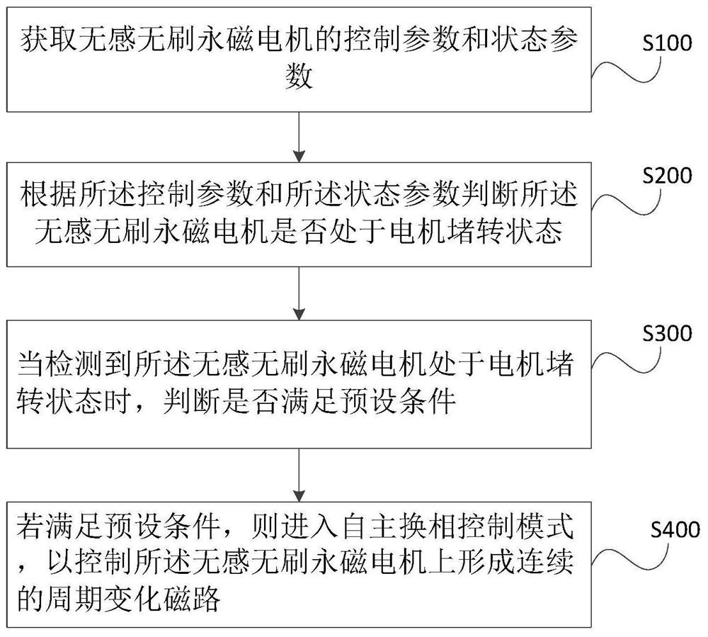
[0032] see figure 1 , in an embodiment of the method for controlling the locked-rotor of the non-inductive brushless permanent magnet motor of the present invention, the processing method includes:

[0033] Step S100, acquiring control parameters and state parameters of the non-sensing brushless permanent magnet motor.

[0034] The control parameters are used to judge whether the non-inductive brushless permanent magnet motor (hereinafter referred to as "motor" in some places) is in the driving state, and the potential state on the control pin can be obtained to judge whether the frequency conversion controller of the motor is in the control output state. When the controller is in the control output state, it is determined that the motor ...


PUM


Abstract

The invention discloses a non-inductive brushless permanent magnet motor locked-rotor control method and a variable frequency controller. The non-inductive brushless permanent magnet motor locked-rotor control method comprises the following steps: acquiring control parameters and state parameters of a non-inductive brushless permanent magnet motor; judging whether the non-inductive brushless permanent magnet motor is in a motor stalling state or not according to the control parameters and the state parameters; when it is detected that the non-inductive brushless permanent magnet motor is in a motor locked-rotor state, judging whether a preset condition is met or not; and if so, entering an autonomous commutation control mode so as to control the non-inductive brushless permanent magnet motor to form a continuous periodic change magnetic circuit. According to the invention, by setting the autonomous commutation output, the equipment can be quickly released, and the torque can be prevented from being output on the same phase for a long time, so that the heating imbalance of the power tube can be avoided, the service life of the variable frequency controller can be ensured, and the adverse effect on the working efficiency can be avoided.

Description

technical field [0001] The invention relates to the technical field of motor control, in particular to a non-sensing brushless permanent magnet motor stall control method and a frequency conversion controller. Background technique [0002] In recent years, permanent magnet brushless motors have developed rapidly due to their good performance such as high power density, simple control, and small volume and mass. The premise of stable motor output speed is accurate commutation. Generally, two methods can be used for commutation. One is to use a position sensor for commutation, and the other is to use a position sensor for commutation. The sensorless brushless permanent magnet motor uses a position sensorless method for commutation. [0003] Motor stalling is a situation in which the motor still outputs torque when the speed is 0 revolutions. Usually, the motor cannot start or stop due to excessive motor load, mechanical failure of the drag, bearing damage and sweeping. In th...

Claims


Application Information

Patent Timeline
Patent Type & Authority Applications(China)
IPC IPC(8): H02P29/024H02P6/18H02P6/34
CPCH02P29/024H02P6/18H02P6/34
Inventor 李保华
Owner 深圳绿威科技有限公司
Why Eureka
Try Eureka