
Gasification/combustion performance testing device for solid fuel under pressurized oxygen-water vapor condition and use method of gasification/combustion performance testing device

A technology of solid fuel and combustion performance, applied in measurement devices, fuel oil testing, analysis materials, etc., can solve problems such as shortages, and achieve the effects of improving combustion efficiency, enriching CO2, and reducing flow fluctuations

Active Publication Date: 2021-09-17
HARBIN INST OF TECH
View PDF10 Cites 2 Cited by
  • Summary
  • Abstract
  • Description
  • Claims
  • Application Information

AI Technical Summary

Problems solved by technology

[0006] The present invention aims to solve the problem of the lack of experimental research systems and methods for performance evaluation of pressurized oxygen-steam combustion, and further provides a solid fuel pressurized oxygen -Gasification / combustion performance test device under water vapor condition and its use method

Method used


Image

  • Gasification/combustion performance testing device for solid fuel under pressurized oxygen-water vapor condition and use method of gasification/combustion performance testing device

Examples


specific Embodiment approach 1

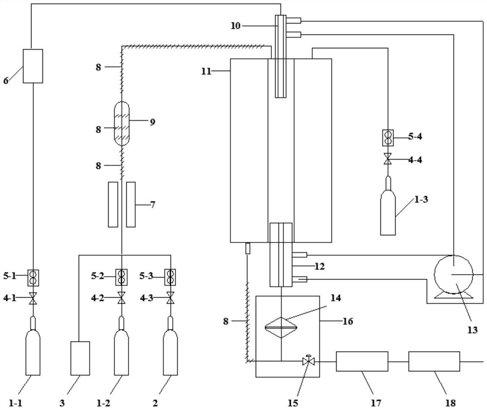
[0032] Specific implementation mode one: combine figure 1 Describe this embodiment in detail. This embodiment is a gasification / combustion performance testing device for solid fuel under pressurized oxygen-steam conditions, which includes a first inert gas tank 1-1, a second inert gas tank 1-2, The third inert gas tank 1-3, oxygen tank 2, high pressure constant flow water injection pump 3, pressurized powder feeder 6, preheating furnace 7, heating belt 8, premix tank 9, oil circulation sampling gun 10, one-dimensional Furnace 11, oil circulation sampling gun 12, gas-solid separator 14, high temperature resistant back pressure valve 15, constant temperature box 16, water vapor separator 17 and flue gas analyzer 18;

[0033] The first inert gas tank 1-1 communicates with the pressurized powder feeder 6, and the pressurized powder feeder 6 communicates with the inlet of the oil circulation sampling gun 10; the high-pressure constant flow water injection pump 3, the second inert g...

specific Embodiment approach 2

[0062] Embodiment 2: This embodiment differs from Embodiment 1 in that: the circulating oil circulation sampling gun 10 and the oil circulation sampling gun 12 are provided with a high-temperature-resistant and heat-conducting oil layer. Others are the same as in the first embodiment.

[0063] In this specific embodiment, the oil circulation sampling gun 10 and the oil circulation sampling gun 12 have oil inlet and outlet ports on the outside and cavities inside.

specific Embodiment approach 3

[0064] Specific embodiment three: the difference between this embodiment and specific embodiment one or two is: use the oil circulation temperature controller 13 to circulate and control the oil layer and the oil layer temperature set outside the oil circulation sampling gun 10 and oil circulation sampling gun 12 . Others are the same as in the first or second embodiment.

[0065] DETAILED DESCRIPTION OF THE PREFERRED EMBODIMENT The oil circulation temperature controller 13 can be heated to not lower than 230°C.


PUM


Abstract

The invention relates to a gasification / combustion performance testing device and a use method thereof, in particular to a gasification / combustion performance testing device for solid fuel under a pressurized oxygen-water vapor condition and a use method of the gasification / combustion performance testing device, aims to solve the problem that an experimental research system and method for pressurized oxygen-water vapor combustion mode performance evaluation are unavailable at present. The device consists of an inert gas tank, an oxygen tank, a high-pressure constant-flow water injection pump, a powder feeder, a preheating furnace, a heating belt, a premixing tank, a sample injection gun, a one-dimensional furnace, a sampling gun, a gas-solid separator, a high-temperature-resistant back pressure valve, a constant-temperature box, a water-vapor separator and a flue gas analyzer. The method comprises the steps that: solid fuel particles are placed in the powder feeder, the inert gas tank is opened, the one-dimensional furnace is heated, the inert gas tank and the oxygen tank are opened, the high-pressure constant-flow water injection pump is started,the high-temperature-resistant back pressure valve is adjusted,the powder feeder is started for thermochemical conversion, and meanwhile gas phase detection is conducted; and the water injection pump, the inert gas tank and the oxygen tank are closed, the high-temperature-resistant back pressure valve is adjusted, heating and residual particle sample and condensate water detection are turned off, and operation is repeated.

Description

technical field [0001] The invention relates to a gasification / combustion performance testing device and a using method thereof. Background technique [0002] The power industry is CO 2 largest source of emissions. CO 2 It has the highest concentration among greenhouse gases and contributes the most to the greenhouse effect. To achieve CO 2 Near zero emissions, promoting clean and efficient development and utilization of energy, the power industry promotes CO 2 Capture and storage technology. [0003] Pressurized oxygen-steam oxygen-enriched combustion technology can realize the separation, enrichment and storage of CO 2 . Existing studies have shown that: In terms of process optimization, due to the lack of flue gas circulation, the thermal power generation system using oxygen-steam combustion technology is simpler, more compact, and more convenient to start and stop than the traditional oxygen-enriched combustion system; in terms of energy efficiency integration, wa...

Claims


Application Information

Patent Timeline
Patent Type & Authority Applications(China)
IPC IPC(8): G01N33/22
CPCG01N33/222
Inventor 赵义军白晨曦张文达谢兴孙绍增邱朋华邓立华冯冬冬吴江全
Owner HARBIN INST OF TECH
Learn More