Automatic fluorescence detection equipment

A detection device and automatic fluorescence technology, applied in the field of fluorescence detection, can solve problems such as low work efficiency, cumbersome work procedures, errors, etc., and achieve the effects of flexible use, simple placement of slides, and high movement accuracy.

Pending Publication Date: 2021-09-17
苏州图墨医疗科技有限公司
View PDF5 Cites 0 Cited by
  • Summary
  • Abstract
  • Description
  • Claims
  • Application Information

AI Technical Summary

Problems solved by technology

[0006] The purpose of the present invention is to provide an automatic fluorescence detection equipment to solve the problem that the fluorescence detection equipment proposed in the above background technology requires staff to manually operate the microscope detection, and manually take pictures, store data information and export data information, and the working procedures are cumbersome. Not only will it cause low work efficiency, but also errors may occur

Method used


Image

  • Automatic fluorescence detection equipment
  • Automatic fluorescence detection equipment
  • Automatic fluorescence detection equipment

Examples


specific Embodiment approach 1

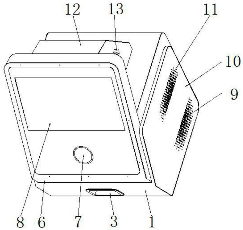
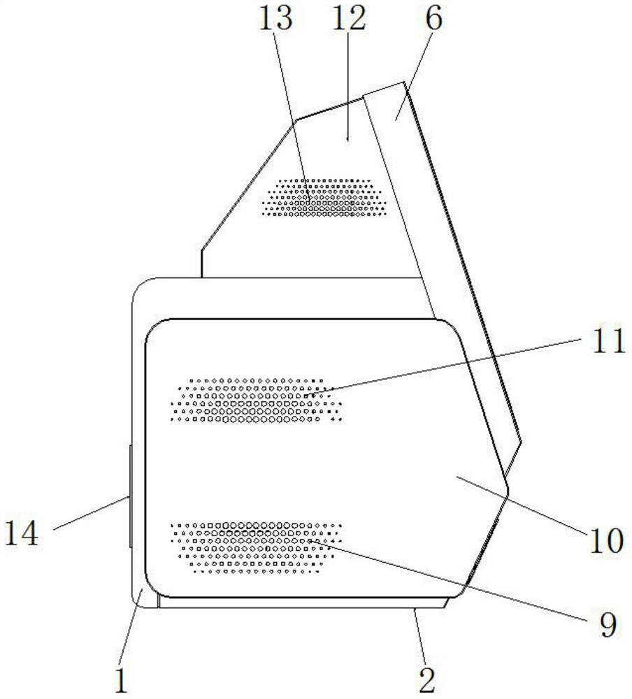
[0038] Specific implementation mode one, refer to Figure 1-13 , the present invention provides a technical solution: an automatic fluorescence detection device, comprising a lower body 1, an upper body 5 and a PC 6, the bottom of the lower body 1 is provided with a base 2, and the upper end of the lower body 1 is equipped with an upper body 5 , the upper body 5 is equipped with a PC 6, and the rear of the PC 6 is provided with a rear cover 12, the left end of the upper surface of the base 2 is vertically fixed with a left fixing plate 15, and the right end of the upper surface of the base 2 is vertically fixed with a right Fixed plate 25, the middle part of left fixed plate 15 and right fixed plate 25 is connected with horizontal frame plate 17, and the upper end of left fixed plate 15 and right fixed plate 25 is all supported on the bottom surface of top plate 28, and the middle part of top plate 28 is equipped with microscope 21, and the lower front end of the microscope 21...

specific Embodiment approach 2

[0040] Specific embodiment two, this embodiment is a further limitation to specific embodiment one, on the mobile platform 27 in the present invention, there are two motion directions of X and Y axes, and each motion direction is controlled by a high-precision stepping motor and a high-precision motor. Driven by the screw rod, it is convenient to move the installation groove 31 on the mobile platform 27 in the left and right or front and rear directions. And it is more flexible to use.

specific Embodiment approach 3

[0041] Embodiment 3. This embodiment is a further limitation of Embodiment 1. In the present invention, the opening groove 3 provided on the front side of the lower body 1 is provided with a scanning port 4, and the front end of the installation groove 31 on the mobile platform 27 It is convenient to protrude a part out of the scanning port 4 when moving forward, so that the inspection staff can place the slide glass on the installation groove 31, and the insertion and extension are fast, the slide glass is easy to place, and the use is more intelligent.


PUM


Abstract

The invention discloses automatic fluorescence detection equipment which comprises a lower machine body, an upper machine body and a PC, a base is arranged at the bottom of the lower machine body, the upper machine body is mounted at the upper end of the lower machine body, the PC is mounted on the upper machine body, a rear cover shell is arranged at the rear part of the PC, a microscope is mounted in the middle of a top plate, a movable plate is arranged at the front end of the lower portion of the microscope, a rear fixed plate is arranged at the rear end of the lower portion of the microscope, an objective lens is installed on the lower portion of the movable plate, the lower end of the objective lens faces a movable platform, and the movable platform is located in the middle of the upper end face of the base. The automatic fluorescence detection equipment is reasonable in structural arrangement, microscopic previewing, photographing and full-automatic sample scanning can be conveniently carried out, data information can be locally stored and can also be exported to external equipment, use is more flexible and intelligent, the two hands of detection workers are liberated, the overall fluorescence detection efficiency is improved, and use is faster and more automatic.

Description

technical field [0001] The invention relates to the technical field related to fluorescence detection, in particular to an automatic fluorescence detection device. Background technique [0002] A fluorescence detection device is built into the flow cytometer used in the medical and biological fields. The fluorescence detection device receives the fluorescence emitted by the fluorochrome of the measurement object through laser irradiation, thereby identifying the type of the measurement object, especially in In the medical field, studies on interactions such as biological binding between proteins are popular, and at the same time, studies on interactions between proteins using fluorescence resonance energy transfer measurement methods are popular. In the past, FRET was measured by changing the fluorescence intensity, but in recent years, various flow cytometers that analyze the object to be measured using the change in the fluorescence relaxation time have been disclosed. ...

Claims


Application Information

Patent Timeline
Patent Type & Authority Applications(China)
IPC IPC(8): G01N15/14
CPCG01N15/1434G01N2015/1452
Inventor 惠开进刘原仲苏明
Owner 苏州图墨医疗科技有限公司
Why Eureka
Try Eureka