
Mechanical closed shock absorber rotation torsion test bench

A technology of torsion testing and shock absorbers, which is applied in the testing of mechanical components, testing of machine/structural components, instruments, etc., can solve the problem of not being able to meet the stringent requirements of torsional shock absorber testing, unfavorable automobile shock absorption performance, and inability to Torsion test and other issues to achieve the effect of improving reliability and stability, improving shock absorption performance, and preventing equipment from being damaged by overheating

Inactive Publication Date: 2021-09-17
安徽精科检测技术有限公司
View PDF0 Cites 2 Cited by
  • Summary
  • Abstract
  • Description
  • Claims
  • Application Information

AI Technical Summary

Problems solved by technology

[0003] After the torsional shock absorber is produced, it is necessary to test the performance of the shock absorber. The test mainly includes two aspects. One is to test the number of rotations of the friction ring of the outer ring of the shock absorber, that is, the rotation reliability. On the one hand, it is to test the torsion times and angles of the driven disc hub inside the shock absorber. The existing shock absorber test bench can only test one of the above two aspects, and cannot rotate on the friction ring. In the process of torsion testing of its internal driven disc hub, it cannot meet the stringent requirements of the torsional shock absorber test, and is not conducive to the improvement of the overall shock absorption performance of the car

Method used


Image

  • Mechanical closed shock absorber rotation torsion test bench
  • Mechanical closed shock absorber rotation torsion test bench
  • Mechanical closed shock absorber rotation torsion test bench

Examples


Embodiment Construction

[0029] The technical solutions in the embodiments of the present invention will be clearly and completely described below in conjunction with the embodiments of the present invention. Apparently, the described embodiments are only some of the embodiments of the present invention, not all of them. Based on the embodiments of the present invention, all other embodiments obtained by persons of ordinary skill in the art without creative efforts fall within the protection scope of the present invention.

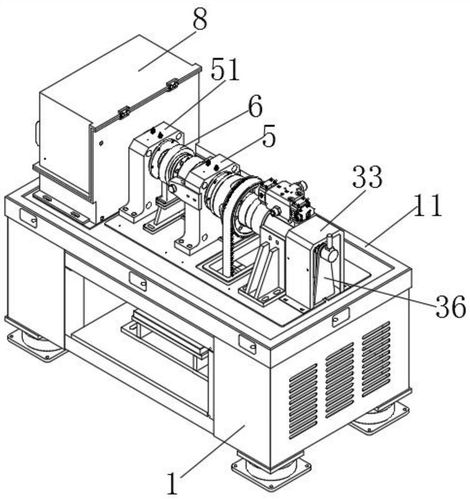
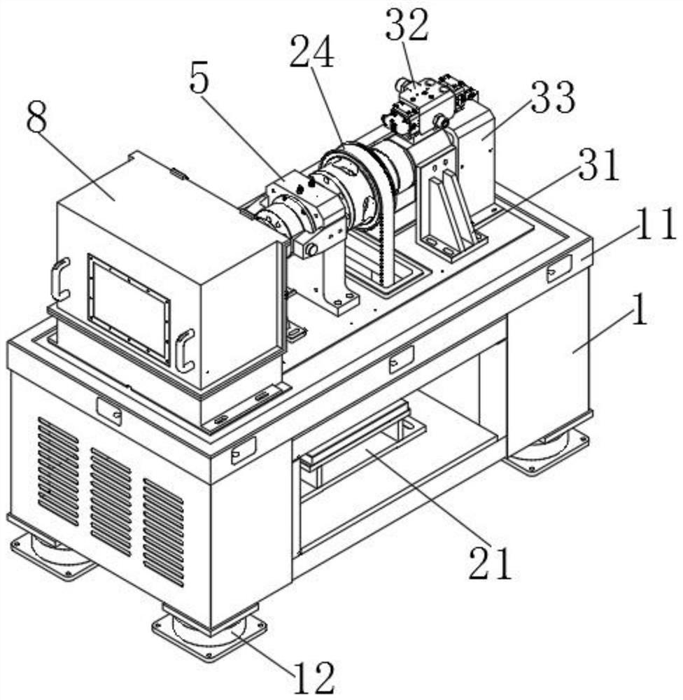
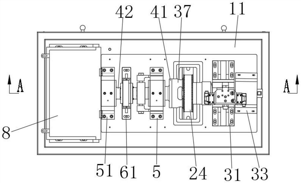
[0030] like figure 1 Shown is a schematic diagram of the overall structure of a mechanically enclosed shock absorber rotation and torsion test bench in the present invention. In the actual production process, the top surface of the support base plate 11 is sleeved from the rotation cylinder 37 to the outside of the test piece box 8. There is a closed shell to prevent the first outer shaft 41 and the second outer shaft 42 from contacting people during the rotation process, which im...


PUM


Abstract

The invention relates to the technical field of shock absorber testing, in particular to a mechanical closed type shock absorber rotation torsion test bench which comprises a base support with a motor installed in an inner cavity and a rotation torque exciter arranged on the base support. A torsion shaft and a rotating cylinder arranged on the outer ring wall of the torsion shaft in a sleeving mode are rotationally connected to the axis of the rotating torque exciter, the rotating cylinder seals the torsion shaft in an inner cavity of the rotating cylinder, and an oil pressure cavity is formed between the rotating cylinder and the torsion shaft. In the invention, the motor is used for driving the rotating cylinder to finally enable the friction ring of the outer ring of the test piece to rotate, and then the electro-hydraulic servo valve is used for driving the inner long shaft to finally enable the inner ring of the test piece to generate advanced and lagged cyclic torsional vibration relative to the outer ring, so that the inner ring and the outer ring generate advanced and lagged phase torsional vibration when the test piece rotates at a high speed; the torque performance of the driven disc hub of the inner ring of the test piece can be tested in the rotating process of the friction ring, and the strict requirements of shock absorber testing are met.

Description

technical field [0001] The invention relates to the technical field of shock absorber testing, in particular to a mechanically enclosed shock absorber rotation and torsion test bench. Background technique [0002] The torsional shock absorber is an important component in the automobile clutch, mainly composed of elastic elements and damping elements, etc. The torsional shock absorber can reduce the torsional stiffness of the joint part between the engine crankshaft and the drive train, thereby reducing the natural frequency of the torsional vibration of the drive train, while increasing The torsional damping of the transmission system can suppress the corresponding amplitude of torsional resonance and attenuate the transient torsional vibration caused by impact, control the torsional vibration of the clutch and transmission shafting when the power transmission assembly is idling, and eliminate the idling noise of the transmission and the noise of the final drive and transmiss...

Claims


Application Information

Patent Timeline
Patent Type & Authority Applications(China)
IPC IPC(8): G01M13/00G01K13/08
CPCG01M13/00G01K13/08
Inventor 张余斌陈春水布图格奇
Owner 安徽精科检测技术有限公司
Learn More