Intercepting ditch, drainage system and manufacturing method of intercepting ditch
A technology of intercepting ditches and systems, applied in the direction of side ditches/curbs, roads, buildings, etc., can solve the problems of noise impact and noise in residential areas, and achieve the effect of ensuring bearing capacity, simple overall structure, and avoiding noise
- Summary
- Abstract
- Description
- Claims
- Application Information
AI Technical Summary
Problems solved by technology
Method used
Image
Examples
Embodiment 1
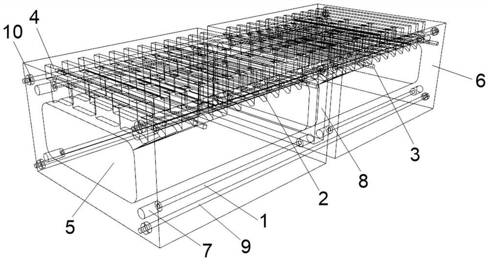
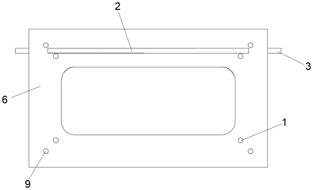
[0032] Such as Figure 1 ~ Figure 3 As shown, this scheme provides a water intercepting ditch, which includes a pipe gallery body 6 connected at both ends. 6 drainage performance. The top of the pipe gallery body 6 is provided at intervals along the length direction of the pipe gallery body 6 with a plurality of drainage outlets 4 communicating with the interior of the pipe gallery body 6. The cross section of the drainage outlet 4 is rectangular, and the width of the drainage outlet 4 is close to the width of the intercepting ditch. , which can maximize the drainage performance of the intercepting ditch, and the drainage port 4 introduces water from the ground into the hydrophobic space 5 .
[0033] In order to avoid the size of the intercepting ditch being too large and occupying the width of the road, the width of the pipe gallery body 6 is D 1 or D 2 ,in, c is the total area of the water at the top of the pipe gallery body 6, B is the width of the drain outlet 4, n ...
Embodiment 2
[0040] This solution provides a drainage system, including a plurality of intercepting ditches in Embodiment 1, and the plurality of intercepting ditches are sequentially arranged in the reserved grooves on the ground, so that the intercepting ditches are located underground to avoid the generation of noise.
[0041] When multiple intercepting ditches are spliced together, due to the errors in the production process of the intercepting ditches, the unevenness of the concrete surface, the influence of road construction, etc., there will be gaps on the splicing surfaces of two adjacent intercepting ditches, and the upper Drainage will seep into the ground through gaps, affecting the drainage performance of the new drainage system. Long-term seepage will also cause safety hazards to passing vehicles on the road.
[0042] Such as figure 1 , figure 2 with Figure 4 As shown, a gasket ring 8 is provided between any two adjacent pipe gallery bodies 6, and the gasket ring 8 adopt...
Embodiment 3
[0045] This proposal provides a method for making an intercepting ditch, which specifically includes the following steps:
[0046] S1. Install the horizontal support rod 2, the anchor rod 3 and the longitudinal support rod 1 in the water intercepting ditch mould;
[0047] S2, pouring UHPC into the intercepting ditch mold, and making the intercepting ditch mold in a vibrating state;
[0048] S3. After the UHPC is solidified, separate the prefabricated intercepting ditch from the intercepting ditch mold
[0049] In step S2, a vibrating table can be used to vibrate the water intercepting ditch mold, so that the UHPC is evenly mixed with the lateral support rod 2, the anchor rod 3, and the longitudinal support rod 1.
PUM
 Abstract
Description
Claims
Application Information
 - R&D
- Intellectual Property
- Life Sciences
- Materials
- Tech Scout
- Unparalleled Data Quality
- Higher Quality Content
- 60% Fewer Hallucinations
Browse by: Latest US Patents, China's latest patents, Technical Efficacy Thesaurus, Application Domain, Technology Topic, Popular Technical Reports.
© 2025 PatSnap. All rights reserved.Legal|Privacy policy|Modern Slavery Act Transparency Statement|Sitemap|About US| Contact US: help@patsnap.com


