
Steam shaping device for stab-resistant garment production

A technology for steam setting and stab-proof clothing, which is applied in the direction of fabric steam/tweed treatment, textile and papermaking, fabric surface trimming, etc. It can solve the problems of not ensuring the flatness of the fabric, affecting the quality of the fabric, and the existence of wrinkles, so as to speed up the setting. Efficiency, ensuring the quality of shaping, and the effect of convenient unloading

Active Publication Date: 2021-09-17
南通市通州区顺行纺织有限公司
View PDF7 Cites 1 Cited by
  • Summary
  • Abstract
  • Description
  • Claims
  • Application Information

AI Technical Summary

Problems solved by technology

[0004] Using clips to clamp the fabric, the fabric cannot be flattened or flattened, and the flatness of the fabric cannot be guaranteed, and there may be wrinkles, which will affect the quality of the fabric after steam setting. Moreover, the method of clamping the fabric will be carried out later. It is also inconvenient to remove the cloth, you need to open all the clips to remove it

Method used


Image

  • Steam shaping device for stab-resistant garment production
  • Steam shaping device for stab-resistant garment production
  • Steam shaping device for stab-resistant garment production

Examples


Embodiment 1

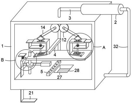
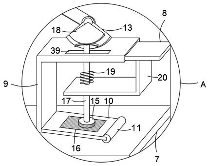
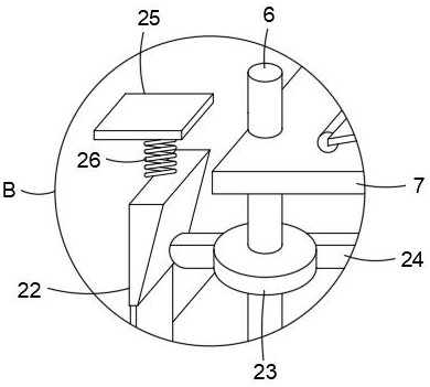
[0032] refer to Figure 1-5 , a steam setting device for the production of stab-resistant clothing, comprising a box body 1, a steam generator 2 is fixedly installed on the upper side wall of the box body 1, an air delivery pipe 3 is connected to the output end of the steam generator 2, and the end of the air delivery pipe 3 part of the upper side wall of the box body 1 and extends to the inside of the box body 1, and two connecting plates 4 are connected to the outer wall of the gas delivery pipe 3, and the opposite sides of the two connecting plates 4 are provided with a connection with the inside of the gas delivery pipe 3. The nozzle 5 and the steam generator 2 work to generate steam through the air pipe 3, and then spray out through the nozzle 5 and contact the cloth on the cover plate 7 to carry out the steam setting work of the cloth;

[0033] A rotary rod 6 is installed inside the box body 1, and a sleeve plate 7 is fixedly set on the outer wall of the upper end of the...

Embodiment 2

[0043] refer to Figure 6 , the difference from Example 1 is:

[0044] The cover plate 7 is composed of an end plate 33 and two adjusting plates 34 which are slidably arranged at the ends of the end plate 33. An adjusting spring 35 is fixedly connected between the two adjusting plates 34. The end plate 33 is equipped with a threaded rod 36 and two guide rods. 37, the threaded rod 36 is threaded with a trapezoidal block 38, the trapezoidal block 38 is an isosceles trapezoidal setting, the trapezoidal block 38 is slidingly sleeved on the outer walls of the two guide rods 37, and the distance between the two adjusting plates 34 is adjusted To prevent work with the installation of different sizes of cloth, turn the threaded rod 36, the trapezoidal block 38 moves inwardly or outwardly, when the trapezoidal block 38 moves inwardly, squeeze the two adjustment plates 34 to move outward, and the distance between the adjustment plates 34 increases. Large, suitable for larger cloth. Whe...


PUM


Abstract

The invention discloses a steam shaping device for stab-resistant garment production. The steam shaping device for stab-resistant garment production comprises a box body, wherein a steam generator is fixedly installed on the side wall of the box body; the output end of the steam generator is connected with a gas conveying pipe; two connecting plates are connected onto the outer wall of the gas conveying pipe; nozzles communicated with the interior of the gas conveying pipe are arranged on the opposite sides of the two connecting plates; a rotating rod is installed in the box body and is fixedly sleeved with a sleeve plate; and the two connecting plates are distributed on the upper side and the lower side of the sleeve plate. According to the steam shaping device for stab-resistant garment production provided by the invention, cloth sleeving the sleeve plate is pushed and pulled to be quickly leveled, so that the situation that the setting quality is affected due to wrinkles of the cloth is avoided; and cloth setting is accelerated by spraying steam up and down, and the cloth can be directly taken down from the sleeve plate after setting, so that discharging is convenient.

Description

technical field [0001] The invention relates to a steam setting device for stab-proof clothing production. Background technique [0002] Anti-stab clothing has the functions of anti-scratch by angular objects, wear resistance, and anti-theft. [0003] Chinese patent document CN109183338A discloses a stab-proof garment production stereotypes device, including a shell, a shock-absorbing base, a support column, a steam generator, a driving device, a heating box, an exhaust fan and an electric heating tube; wherein, a nozzle is arranged in the shell , rotating shaft, turntable, first connecting piece, rotating shaft, fan plate, second connecting piece, elastic piece and clip; the casing is provided with a drain port; the steam generator is connected to the nozzle through the air pipe; the driving device is connected to the rotating shaft by transmission; the rotating shaft The fan plate is installed on the top; the rotating shaft is connected to the rotating shaft by transmissi...

Claims


Application Information

Patent Timeline
IPC IPC(8): D06C15/00
CPCD06C15/00D06C2700/10D06C2700/13
Inventor 王奔濠
Owner 南通市通州区顺行纺织有限公司
Learn More