Eureka AIR delivers breakthrough ideas for toughest innovation challenges, trusted by R&D personnel around the world.

Textile conveying cooling alarm device

An alarm device and textile technology, applied in textiles and papermaking, electrical transmission signal system, processing textile material carriers, etc., can solve the problems of no cooling function, unable to stop textile transportation, etc., and achieve the effect of convenient use of equipment

Active Publication Date: 2021-09-17
临沂临港国有资产运营集团有限公司
View PDF12 Cites 0 Cited by
  • Summary
  • Abstract
  • Description
  • Claims
  • Application Information

AI Technical Summary

Problems solved by technology

[0005] In order to overcome the shortcomings of the current textiles that have no cooling function when the temperature is too high and cannot stop the transportation of textiles at the same time, the technical problem of the present invention is to provide an alarm function that can cool the textiles that are conveyed and When the temperature of the textile is too high, the textile conveying cooling alarm device that automatically stops conveying

Method used


Image

  • Textile conveying cooling alarm device
  • Textile conveying cooling alarm device
  • Textile conveying cooling alarm device

Examples


Embodiment 1

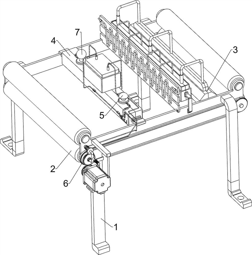
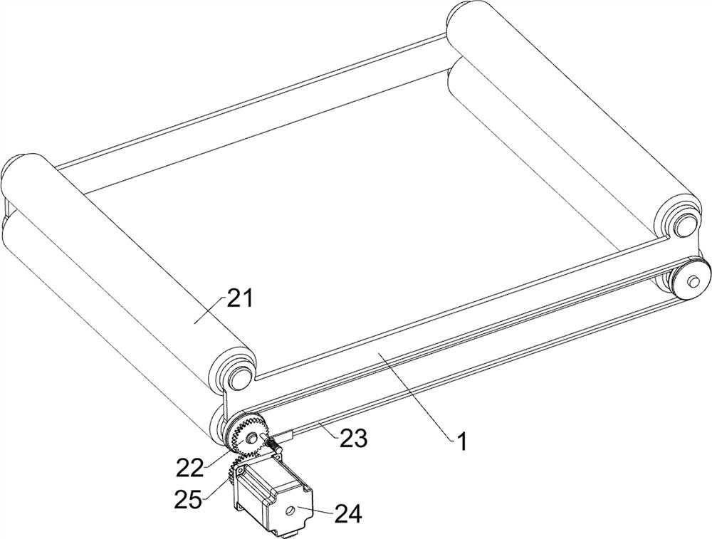
[0027] A textile conveying cooling alarm device, such as Figure 1-Figure 3 As shown, it includes a support 1, a conveying assembly 2 and a cooling mechanism 3. The conveying assembly 2 for textile conveying is installed on the top of the support 1, and the cooling mechanism 3 for cooling by blowing is installed on the right side of the top of the support 1.

[0028] When the textile needs to be conveyed, the textile is first placed between the conveying components 2, and then the conveying component 2 is controlled to start working to convey the textile. During the conveying of the textile, the cooling mechanism 3 is controlled to stop working. The temperature is automatically adjusted to cool down the textiles, and after the textiles are conveyed, the conveying assembly 2 and the cooling mechanism 3 are controlled to stop working.

[0029] The conveying assembly 2 includes a drum 21, a first gear 22, a drive pulley set 23, a reduction motor 24 and a second gear 25, and the u...

Embodiment 2

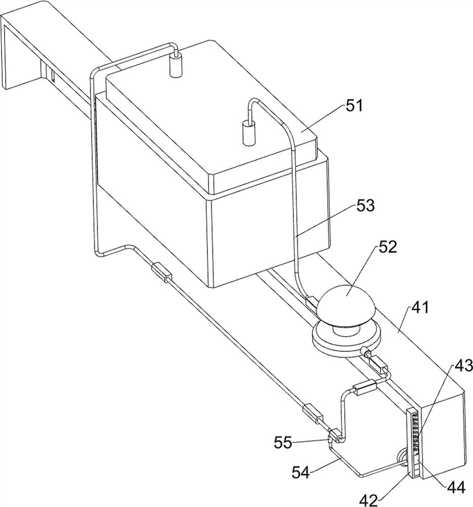
[0034]On the basis of Example 1, such as figure 1 , Figure 4 , Figure 5 , Figure 6 and Figure 7 As shown, a reaction mechanism 4 is also included. A reaction mechanism 4 is installed on the left side of the top of the support 1. The reaction mechanism 4 includes a mounting frame 41, a slide rail 42, a first spring 43, a slider 44 and an air bag 45. The top left side of the support 1 The side is fixedly connected with the installation frame 41 by bolts, and the front and rear sides of the installation frame 41 are provided with slide rails 42, and the slide rails 42 are all slidably provided with sliders 44, and a first An air bag 45 is connected between the spring 43 and the slider 44, and an inert gas is housed in the air bag 45.

[0035] After the textile is cooled down, when passing through the airbag 45, if the temperature of the textile is still too high, the airbag 45 will expand, and the diameter of the airbag 45 becomes larger, the first spring 43 is compressed...


PUM


Abstract

The invention relates to an alarm device, in particular to a textile conveying cooling alarm device. The textile conveying cooling alarm device has an alarm function, can cool conveyed textiles and automatically stops conveying when the temperature of the textiles is too high. The textile conveying cooling alarm device is characterized by comprising a support, a conveying assembly and a cooling mechanism; the conveying assembly is installed on the support and conveys the textiles in a rotating mode; and the cooling mechanism is mounted on the support and is used for cooling in an air blowing manner. Through the characteristics of inert gas, the textile cooling speed can be automatically adjusted, and the equipment is very convenient to use; through a sound reminding mechanism and a visual reminding mechanism, sound and light are matched for reminding, and higher safety can be achieved; and when the temperature of the textile is too high, a second gear and a first gear are disconnected, the equipment can automatically stop working, and the conveyed textile can be better protected.

Description

technical field [0001] The invention relates to an alarm device, in particular to an alarm device for cooling textiles. Background technique [0002] Textiles are products made of textile fibers through processing and weaving. China is one of the earliest countries in the world to produce textiles. The main producing areas are Puyuan in Zhejiang and Qinghe in Hebei. During the production process of textiles, they need to be transported. During the process of textiles transmission, there is a base temperature. This temperature is also the processing temperature to ensure the stable yield of textiles. Therefore, it is necessary to carry out Monitor alarms. [0003] The patent application announcement number is CN104422546A, which discloses a temperature measurement and alarm device for textile transmission, including a base, on which guide rollers are arranged, and every two guide rollers are arranged up and down to form a transmission part, and the textiles are transported f...

Claims


Application Information

Patent Timeline
Patent Type & Authority Applications(China)
IPC IPC(8): D06C7/00D06B23/04G08B7/06
CPCD06C7/00D06B23/04G08B7/06
Inventor 张怀旺
Owner 临沂临港国有资产运营集团有限公司
Why Eureka
Eureka Blog
Learn More