Crease-resistant device for stamping forming of large curved-surface thin-wall component
A thin-walled member, stamping forming technology, applied in the field of stamping forming, can solve the problems of high maintenance cost and complex mold shape, and achieve the effects of reducing free surface area, improving forming accuracy, improving stress state and bulging components
- Summary
- Abstract
- Description
- Claims
- Application Information
AI Technical Summary
Problems solved by technology
Method used
Image

Examples
Embodiment 1
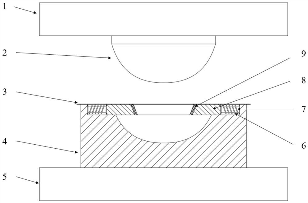
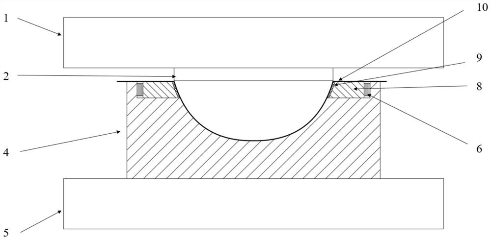
[0027] In this embodiment, the bottom of the rocket storage tank is taken as the experimental object, and the anti-wrinkle device is mainly composed of a punch 2, a die 4, a coil spring 6, a wedge 8 and an elastic ring 9. The wedge 8 moves relative to the die 2 through the wedge guide rod 7 , the coil spring 6 is arranged in the wedge guide rod 7 , and the elastic ring 9 is arranged outside the wedge 8 . before molding figure 1 As shown, the coil spring 6 is in a free state, restricting the wedge 8 at a specified position. When the punch moves downward, the wedge 8 moves horizontally inward along the wedge guide rod 7 due to pressure and compresses the coil spring. 6, such as figure 2 As shown, the compression of the coil spring 6 gives a reverse force to the wedge 8, so that the elastic ring 9 is always attached to the sheet 3 during forming, and finally a formed component is obtained.
[0028] In this embodiment, the anti-wrinkle method of stamping and forming large-scale...
Embodiment 2
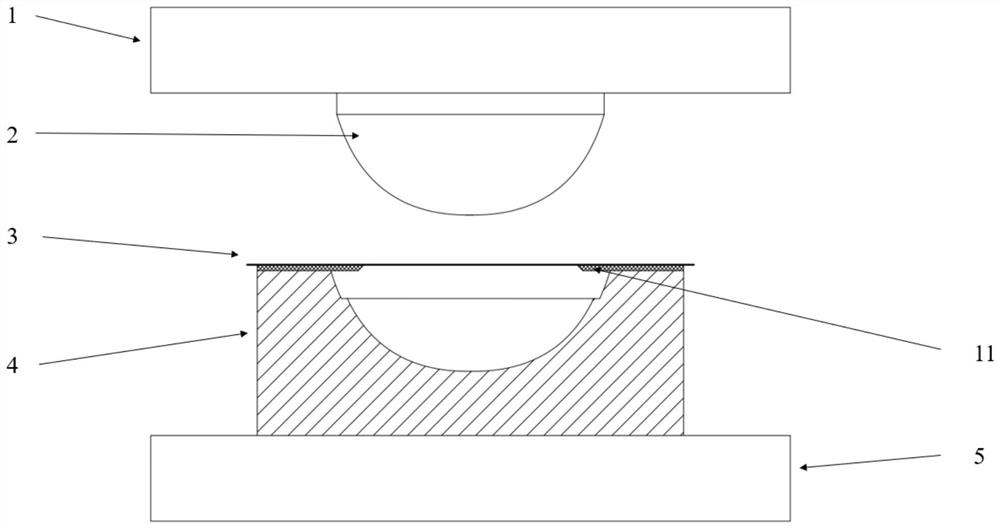
[0030] In this embodiment, the bottom of the rocket storage tank is used as the experimental object, and the anti-wrinkle device replaces the coil spring, wedge, and elastic ring in Embodiment 1 with an integral elastic pad 11 . before molding image 3 As shown, the elastic pad is not affected by force; when the punch moves downward, the elastic pad will move along with the sheet, and due to the reaction force of the elastic pad, the sheet will always stick to the elastic pad, changing the original stress of the sheet state, reducing the tensile stress of the sheet in the wrinkled area, and suppressing the wrinkling of the sheet, the final result of forming is as follows Figure 4 As shown, the elastic pad 11 will finally cooperate with the groove reserved in the die 4, so that the blank can be stamped into a specified shape.
[0031] In this embodiment, the anti-wrinkle method of stamping large-scale curved thin-walled components adopts an integral elastic pad, which replace...
Embodiment 3
[0033] In this embodiment, the reflective surface of the satellite is used as the experimental object. In order to meet the situation that the convex and concave molds of the mold are inverted, the anti-wrinkle device in this embodiment is as follows: Figure 5 shown, with figure 1 Similarly, the way of wedges and springs is also used. When the die descends with the press beam 1, it first contacts with the blank holder 12, and then moves downward along the hydraulic tappet together with the blank holder. During the whole process, The punches are all fixed, and the forming results are as follows Figure 6 shown.
[0034] The anti-wrinkle method of stamping large-scale curved thin-walled components in this embodiment is similar to that of Embodiment 1. The relative movement of the elastic elements is used to achieve the effect that the mold changes with the deformation of the sheet metal, so that the unsupported area at the beginning of the forming stage is always elastically s...
PUM
 Abstract
Description
Claims
Application Information
 - R&D
- Intellectual Property
- Life Sciences
- Materials
- Tech Scout
- Unparalleled Data Quality
- Higher Quality Content
- 60% Fewer Hallucinations
Browse by: Latest US Patents, China's latest patents, Technical Efficacy Thesaurus, Application Domain, Technology Topic, Popular Technical Reports.
© 2025 PatSnap. All rights reserved.Legal|Privacy policy|Modern Slavery Act Transparency Statement|Sitemap|About US| Contact US: help@patsnap.com