Glass powder barreling device and mixed processing equipment adopting same

A technology of glass powder and tumbling, which is applied in the direction of grain processing, etc., and can solve the problems of affecting the service life, easy to drop, wear and tear of the tank body and metal sheet, and achieve the effects of simple and convenient operation, improved working environment, and increased service life

Active Publication Date: 2021-09-17
ANHUI XINXU SEMICON
View PDF6 Cites 0 Cited by
  • Summary
  • Abstract
  • Description
  • Claims
  • Application Information

AI Technical Summary

Problems solved by technology

This can realize the rolling of the tank body, but since the driving wheel and the driven wheel are a round rod, the position of the ceramic tank cannot be fixed while rolling, and it is easy to fall
The general treatment method is to fix the two ends with fixed metal sheets, but due to long-term friction, the tank body and the metal sheets will be worn, which will eventually affect the service life. In addition, the noise in the actual operation process is very large.

Method used


Image

  • Glass powder barreling device and mixed processing equipment adopting same
  • Glass powder barreling device and mixed processing equipment adopting same
  • Glass powder barreling device and mixed processing equipment adopting same

Examples


Embodiment approach

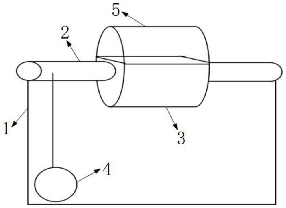
[0031] (1) The motor device drives the driving wheel, and the driving wheel drives the driven wheel on the metal rod to rotate through the belt or chain.

[0032] (2) There is a large fixed ferrule structure 3 in the middle of the metal rod, and there is also a movable ferrule structure. The movable ferrule structure 5 and the fixed ferrule structure 3 cooperate with each other. The fixed ferrule structure 3 can be a circle with a superior arc in cross section. shaped structure, the movable ferrule structure 5 can be a circular structure with a minor arc in section.

[0033] (3) During use, the configured ceramic jar is put into the circular fixed ferrule structure 3, and the movable ferrule structure 5 is covered on the top, and fastened with buckles on both sides.

[0034] (iv) Start the motor device, the ceramic pot can rotate silently, and the inner glass powder can realize the rolling action.

Embodiment 2

[0036] In the structural configuration of the present invention:

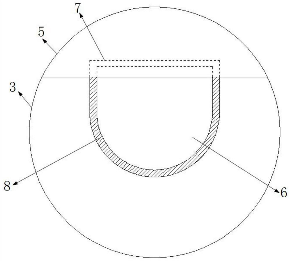
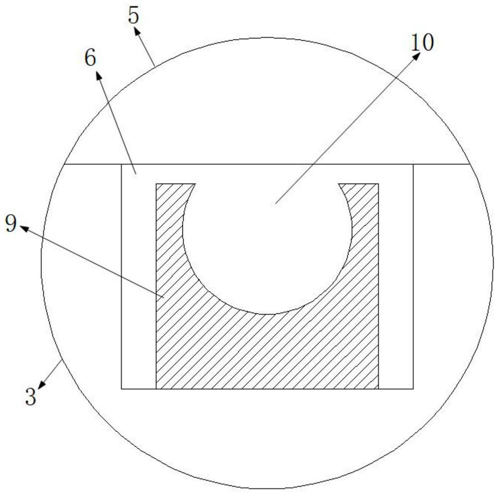
[0037] The external shape of the ceramic tank is cylinder, cuboid, sphere or any polyhedron shape. Cooperating with the outer shape of the ceramic pot, the groove body shape of the ferrule inner groove 6 in the fixed ferrule structure 3 is also cylindrical, cuboid, sphere or any polyhedron shape.

[0038] The movable ferrule structure 5 is provided with a limit reinforcement structure 7, and the limit reinforcement structure 7 matches the position of the opening side of the ferrule inner groove 6 in the fixed ferrule structure 3.

[0039] The surface layer of the ferrule inner groove 6 and the surface layer of the limit reinforcement structure 7 are all provided with a layer of anti-skid pad 8, the anti-skid pad 8 can be a rubber pad, and the rubber pad and the surface layer of the ferrule inner groove 6 and the surface layer of the limit reinforcement structure 7 are bonded agent bonding.

[0040] The ferrul...


PUM


Abstract

The invention discloses a glass powder barreling device, and relates to the technical field of semiconductor device processing. The glass powder barreling device comprises a power device, a support frame and a ceramic pot which is used for mixing glass powder, a group of rotating shaft rods are rotationally arranged on the upper side of the support frame, the power device is connected with the rotating shaft rods through a transmission structure, the opposite ends of the inner sides of the group of rotating shaft rods are jointly and fixedly connected with a fixed clamping sleeve structure, an open-type clamping sleeve inner groove is formed in the fixed clamping sleeve structure, the ceramic pot is placed in the clamping sleeve inner groove of the fixed clamping sleeve structure, and a movable clamping sleeve structure located on the opening side of the clamping sleeve inner groove is movably installed on the fixed clamping sleeve structure. According to the glass powder barreling device, friction between the ceramic pot and other parts of equipment is avoided, basically no wear can be realized, the service lives of the ceramic pot and the equipment are greatly prolonged, mute operation is realized, and the operation environment is improved.

Description

technical field [0001] The invention belongs to the technical field of semiconductor device processing, and in particular relates to a glass powder rolling device and a mixing processing equipment, which are used for mixing processing of glass powder and photoresist. Background technique [0002] In the process of diode chip processing, glass powder is needed to passivate the PN junction, and the glass needs to be mixed with photoresist and glass powder for a long time before it can evenly cover the surface of the wafer, which requires the use of barrel grinding device, that is, mix glass powder and photoresist into a ceramic tube, cover the lid, and then put the ceramic tube into a tumbling device for tumbling. [0003] In the existing technology, the motor drives the driving wheel through the belt, and then puts the circular ceramic pot between the driving wheel and the driven wheel. When the motor is turned on, the driving wheel rotates, and the pipe body and the driven w...

Claims


Application Information

Patent Timeline
Patent Type & Authority Applications(China)
IPC IPC(8): B02C17/18B02C17/00B02C17/24
CPCB02C17/18B02C17/00B02C17/24
Inventor 汪良恩李建利汪曦凌
Owner ANHUI XINXU SEMICON
Why Eureka
Try Eureka