
Motion capture device based on sensor array and posture recognition method thereof

A sensor array and motion capture technology, applied in the field of motion capture, can solve problems such as device paralysis and unusability

Pending Publication Date: 2021-09-14
ZHEJIANG UNIV OF TECH
View PDF11 Cites 0 Cited by
  • Summary
  • Abstract
  • Description
  • Claims
  • Application Information

AI Technical Summary

Problems solved by technology

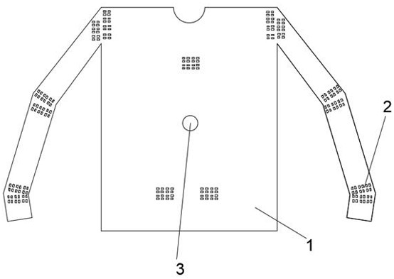
[0004] In view of the problems existing in the prior art, the object of the present invention is to provide a sensor array-based motion capture device and its gesture recognition method, a clothing-like motion capture device distributed using arrayed thin-film pressure sensors, during the wearing process, The communication of tension, shear and other parameters due to movement, using neural network training, can spontaneously couple a better running result; it not only makes up for the instability of the geomagnetic field and poor coupling during use. Action drift can also solve the problem of device paralysis and inability to use due to the lack of sensors in use

Method used


Image

  • Motion capture device based on sensor array and posture recognition method thereof
  • Motion capture device based on sensor array and posture recognition method thereof
  • Motion capture device based on sensor array and posture recognition method thereof

Examples


Embodiment 1

[0046] Forearm lift up

[0047] Such as Figure 4-7 As shown, the film sensor array is formed into an array by the first film sensor 6, the second film sensor 7, the third film sensor 8, the fourth film sensor 9, the fifth film sensor 10, and the sixth film sensor 11. When the forearm of the forearm is lifted upwards, the sensor array in the clothes worn above the forearm will be forced to squeeze due to the movement of the arm, that is, shrink, and the first film sensor 6 and the second film sensor 7 will be squeezed downward. The pressure movement causes the third thin film sensor 8 and the fourth thin film sensor 9 to shrink, at this time the third thin film sensor 8 and the fourth thin film sensor 9 will generate a displacement ∆A, and at the same time generate a voltage array group and send it to the parameter summary sending mechanism 3. At the same time, the sensor array in the clothes worn under the forearm will be forced to stretch due to the movement of the arm, tha...

Embodiment 2

[0049] Medial rotation of the forearm

[0050] Such as Figure 8-9 As shown, when the forearm of the user rotates independently at this time, the sensor array in the clothes worn above the forearm will produce forced motion due to the movement of the arm, that is, rotation will be generated. At this time, the first film sensor 6 and the second film The sensor 7 will be squeezed to the left, causing the third film sensor 8 and the fourth film sensor 9 to shrink. At this time, the first film sensor 6 and the second film sensor 7 will produce a displacement ∆C, while the third film sensor 8 and the fourth film sensor 9 produce another distorted displacement ∆D; at this time, the first film sensor 6 and the second film sensor 7 will produce a positive pulling force δc, the third film sensor 8 and the fourth film sensor 9 A shear force ε will be generated; the sensor group will output a set of current arrays; at the same time, the background software will communicate, and the gene...


PUM


Abstract

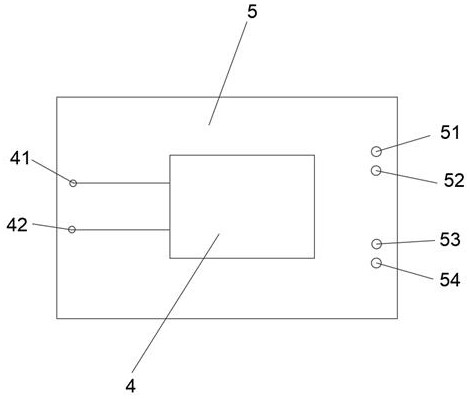
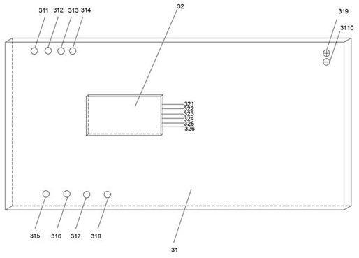
The invention discloses a motion capture device based on a sensor array and a posture recognition method thereof, and belongs to the technical field of motion capture, the motion capture device comprises an elastic garment, a group of thin film pressure sensors, a parameter summarizing and sending mechanism and a ground base station, the thin film pressure sensors are uniformly arranged at arm joints of the elastic garment in the radial direction and the circumferential direction, the parameter summarizing and sending mechanism is arranged at the center of the elastic clothes, the thin film pressure sensors are electrically connected with the parameter summarizing and sending mechanism, the parameter summarizing and sending mechanism is in wireless communication with a ground base station, and the thin film pressure sensors are connected through thin wires. By the adoption of the technical scheme, the clothes-like motion capture device formed by distributing the array type thin film pressure sensors is used, in the using and wearing process, the neural network is used for training voltage flow group parameters generated due to motion, and actions can be automatically fitted and displayed on a ground base station.

Description

technical field [0001] The invention belongs to the technical field of motion capture, and in particular relates to a sensor array-based motion capture device and a posture recognition method thereof. Background technique [0002] Currently on the market, when performing motion capture, a wearable multi-single-point multi-axis sensor coupling motion posture capture system is commonly used. These motion capture systems, due to the need for parameter coupling of multiple sensors, easily lead to relatively large sensor errors. , and due to the existence of the magnetometer of the nine-axis sensor, it is easily affected by the earth's magnetic field; at present, the coupling of the magnetometer, accelerometer and gyroscope in the nine-axis sensor is still in its infancy, and the coupling parameters are not ideal. The parameters of the magnetometer are easy to drift, and it is related to the selected position and different indoor environments; the current magnetometer cannot with...

Claims


Application Information

Patent Timeline
IPC IPC(8): G06F3/01G01C21/00G01L1/00
CPCG06F3/011G01C21/00G01L1/005
Inventor 唐迪金伟杰车婧琦黄喜鹏
Owner ZHEJIANG UNIV OF TECH
Learn More