Multifunctional pilot-operated safety valve
A pilot-operated safety valve and multi-functional technology, which is applied in the field of multi-functional pilot-operated safety valves, can solve problems such as the influence of the surrounding environment, and achieve the effects of long service life, high discharge accuracy and reliable sealing
- Summary
- Abstract
- Description
- Claims
- Application Information
AI Technical Summary
Problems solved by technology
Method used
Image


Examples
Embodiment 1
[0032] As a preferred embodiment of the present invention, refer to the accompanying figure 1 , figure 2 and image 3 As shown, this embodiment discloses a multi-function pilot-operated safety valve, including a main valve part and a pilot valve part, and the main valve part and the pilot valve part are assembled into one; figure 1 As shown, it includes valve body 1, main valve sleeve 2, main valve core 3, valve stem 4, cylinder block 5, main valve piston 6, pilot valve seat 7, pilot valve disc 8, piston shaft 9, A medium inlet 12 and a medium outlet 13 are provided on the pressure guiding pipe 10 and the pilot valve adjusting assembly 11 and the valve body 1 .
[0033] like figure 2 As shown, the main valve sleeve 2 is assembled in the valve body 1 by the cylinder block 5, and the cylinder block 5 and the valve body 1 are fixedly assembled together; the main valve sleeve 2 is formed between the cylinder block 5 and the main valve sleeve 2 for assembling the main valve T...
Embodiment 2
[0039] As another preferred embodiment of the present invention, this embodiment is a specific implementation that is further perfected on the basis of Embodiment 1, and the details are as follows:
[0040] refer to image 3 As shown, as an implementation of the present embodiment, the passage through which the valve flap cavity 22 on the pilot valve seat 7 communicates with the piston upper cavity 17 is a damping passage. The damping passage on the pilot valve seat 7 further improves the opening sensitivity and precision of the main valve.
[0041] As another implementation of this embodiment, the end of the cylinder body 5 connected to the valve body 1 is provided with a channel hole II 26 , and the channel hole II 26 is connected to the cavity on the main valve sleeve 2 in the valve body 1 . Correspondingly, after the cylinder body 5 is assembled on the valve body 1 , the passage hole II 26 on the cylinder body 5 and the cavity on the main valve sleeve 2 form the spring ca...
Embodiment 3
[0043] As another preferred embodiment of the present invention, this embodiment is a specific implementation that is further perfected on the basis of Embodiment 1 and / or Embodiment 2, and the details are as follows:
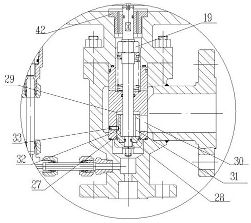
[0044] As an implementation of this embodiment, the main valve core 3 includes an upper valve core 27 and a lower valve core 28, the lower valve core 28 is connected to the bottom of the upper valve core 27, and the upper valve core 27 is connected to the valve stem 4, And the upper valve core 27 is embedded in the main valve valve sleeve 2 and installed. The lower end of the main valve valve sleeve 2 is provided with a valve core cavity 29 for the upper valve core 27 to be nested. Window 30. The split structure of the upper spool 27 and the lower spool 28 is equivalent to setting a double seal. If there is a problem with the sealing pair at the bottom of the lower spool 28 and the main valve sleeve 2, the upper spool 27 can still be closed The purpose of the ...
PUM
 Abstract
Description
Claims
Application Information
 - R&D
- Intellectual Property
- Life Sciences
- Materials
- Tech Scout
- Unparalleled Data Quality
- Higher Quality Content
- 60% Fewer Hallucinations
Browse by: Latest US Patents, China's latest patents, Technical Efficacy Thesaurus, Application Domain, Technology Topic, Popular Technical Reports.
© 2025 PatSnap. All rights reserved.Legal|Privacy policy|Modern Slavery Act Transparency Statement|Sitemap|About US| Contact US: help@patsnap.com