Bidirectional diaphragm pump without distributing valve

A technology for diaphragm pumps and flow distribution valves, which is applied to pumps, parts of pumping devices for elastic fluids, pump components, etc., and can solve problems such as easy crystallization, increased difficulty of development work, and increased system costs

Pending Publication Date: 2021-09-14
湖北天雄科技股份有限公司
View PDF0 Cites 0 Cited by
  • Summary
  • Abstract
  • Description
  • Claims
  • Application Information

AI Technical Summary

Problems solved by technology

[0003] In the diesel engine SCR exhaust aftertreatment system, urea is generally added by motor diaphragm pump or gear pump. The National VI standard stipulates that when the diesel engine is shut down, the residual urea solution in the pipeline and metering solenoid valve (nozzle) cannot be injected into the exhaust pipe. Therefore, the supply unit of the urea pump must have the function of back pumping or back blowing, but—for the diaphragm pump, this structure has good sealing performance and no product leakage, but it can only realize one-way operation and output liquid, and cannot reverse operation, so the urea The pump supply unit must be equipped with a reverse pumping solenoid valve and a reverse pumping circuit, which not only increases the cost of the system, but also complicates the urea solution flow channel, which is easy to crystallize and block the urea in the flow channel. The stuck urea liquid solenoid valve increases the difficulty of the development work; for the gear pump, this structure can realize the forward and reverse movement to realize the output and reverse pumping of the liquid, but the sealing is not good, and it is easy to cause leakage

Method used


Image

  • Bidirectional diaphragm pump without distributing valve
  • Bidirectional diaphragm pump without distributing valve
  • Bidirectional diaphragm pump without distributing valve

Examples


Embodiment Construction

[0022] The present invention will be further described below in conjunction with the accompanying drawings and embodiments.

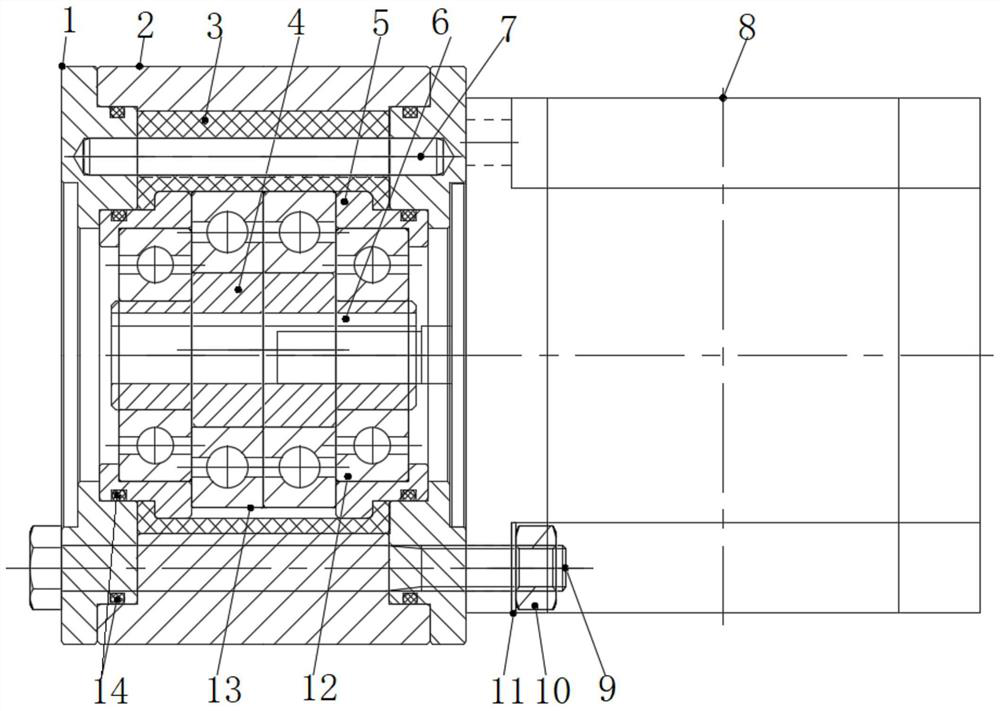
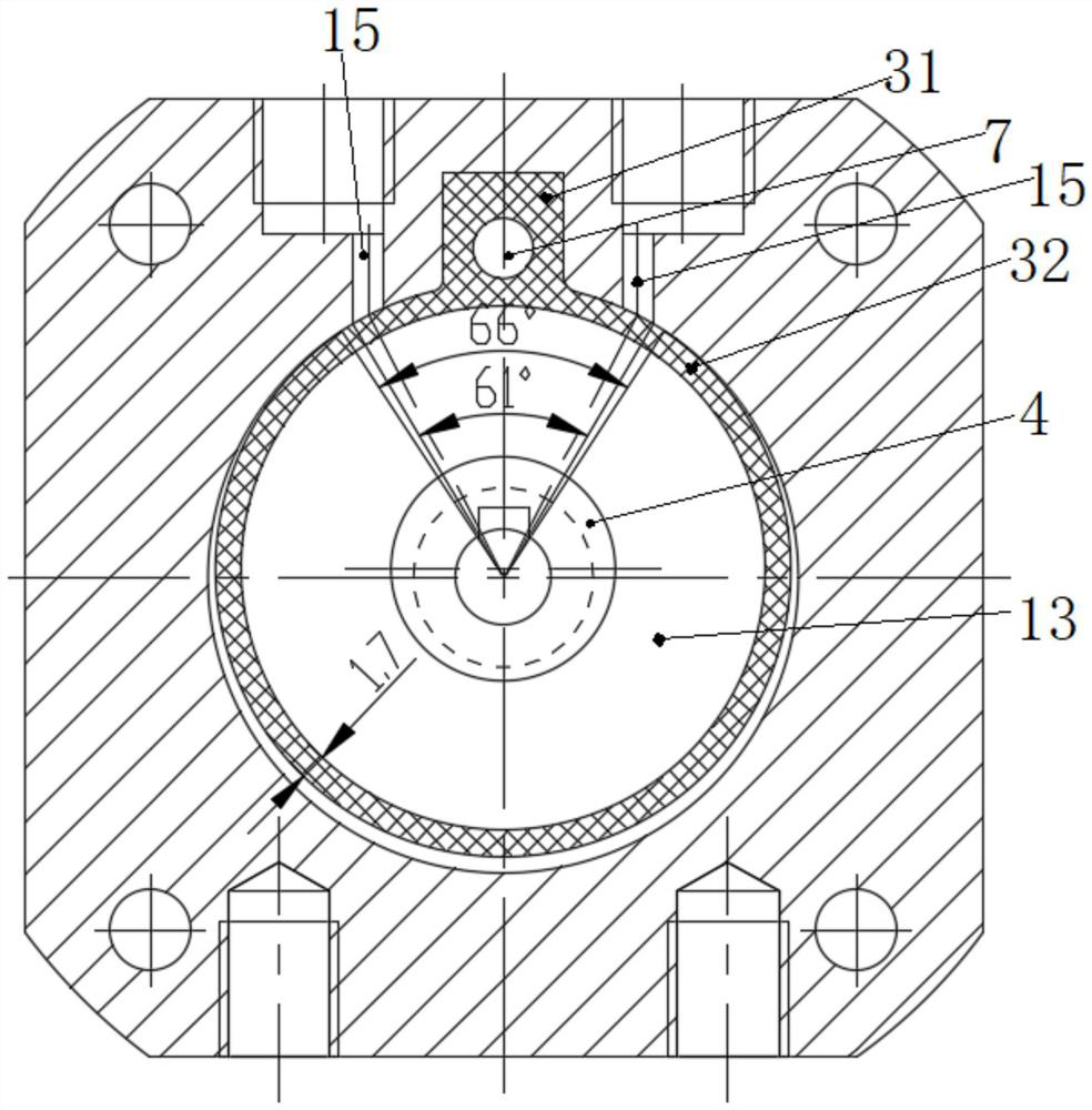
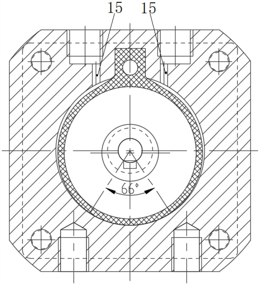
[0023] Such as Figure 1 to Figure 3 As shown, a two-way diaphragm pump without flow distribution valve includes a housing and a motor 8 installed together. Two flow channels 15 are opened on the outer wall of the housing, and an eccentric shaft 4 driven by the motor 8 is arranged inside. Diaphragm 3 for grinding materials, the eccentric section of eccentric shaft 4 is covered with extrusion bearing 13, the two ends of diaphragm 3 are axially positioned and sealed with the housing, and the radial side of diaphragm 3 is an anti-skid protrusion 31 connected with the housing. The other side is the ring sleeve 32 that is set on the extrusion bearing 13. The two flow channels 15 respectively extend to both sides of the anti-slip protrusion 31 on the inner wall of the housing and are isolated by the ring sleeve 32 and are always disconnected. One side is in ...


PUM


Abstract

The invention discloses a bidirectional diaphragm pump without a distributing valve. The bidirectional diaphragm pump comprises a shell and a motor which are installed together, wherein two flow channels are formed in the outer wall of the shell, an eccentric shaft driven by the motor and a diaphragm made of flexible wear-resistant materials are arranged in the shell, the eccentric section of the eccentric shaft is sleeved with an extrusion bearing, and the two ends of the diaphragm and the shell are axially positioned and sealed; the radial side of the diaphragm is provided with an anti-skid protrusion connected with the shell, the other side of the diaphragm is provided with a ring sleeve arranged on the extrusion bearing in a sleeving manner, the two flow channels extend to the two sides of the anti-skid protrusion on the inner wall of the shell respectively and are isolated by the ring sleeve to be not communicated all the time, the eccentric side of the ring sleeve makes contact with the inner wall of a pump body, and the other side of the ring sleeve and the inner wall of the pump body form a working cavity; and when the motor drives the eccentric shaft, the extrusion bearing extrudes the ring sleeve to make continuous contact with the inner wall of the pump body in the eccentric movement direction. According to the bidirectional diaphragm pump, a brand new diaphragm structure is adopted, and a one-way flow distributing valve does not need to be arranged, so that two-way suction can be achieved; and a crank-link mechanism is not needed, so that reliability and stability are improved, and the application effect is good.

Description

technical field [0001] The invention relates to a diaphragm pump, in particular to a bidirectional diaphragm pump without a distribution valve. Background technique [0002] The principle of the diaphragm pump is to use the elastic characteristics of the diaphragm to make the diaphragm move back and forth, driving the volume chambers on both sides to produce alternating changes in air pressure, so as to realize continuous suction and discharge of liquid. Due to the limitations of the existing structure, in order to ensure the continuous suction and discharge of liquid, the current diaphragm pump needs to be equipped with flow distribution mechanisms such as check valves, so it cannot operate in reverse. This defect will cause a series of problems in specific applications, such as: [0003] In the diesel engine SCR exhaust aftertreatment system, urea is generally added by motor diaphragm pump or gear pump. The National VI standard stipulates that when the diesel engine is shu...

Claims


Application Information

Patent Timeline
Patent Type & Authority Applications(China)
IPC IPC(8): F04B43/04F04B53/16F04B53/22F04B53/00F01N3/20F16J15/10
CPCF04B43/04F04B53/16F04B53/22F04B43/0054F01N3/2066F16J15/10F01N2610/02F01N2610/1433
Inventor 廖义德周翔魏柏杨高立志陈祥
Owner 湖北天雄科技股份有限公司
Why Eureka
Try Eureka