
Patsnap Eureka
For R&D, Patsnap Eureka makes reading and utilizing patents & technical documents easy.
Patsnap Eureka AIR
Designed for self-driven R&D workflows. Generate viable solutions, solve complex R&D challenges, empower your innovation with AI.

Patsnap Eureka Materials
Designed for material experts only. Revolutionize your material R&D, from search, analyze, to developing new materials.

TechResearch
Generate reliable direction feasibility study reports for your R&D in just a few steps.

TechSeek
Discover and master advanced knowledge NOW. Basics, ideas, possibilities, all at once.

TechMind
As an expert in R&D Theories, TechMind can generates customized viable solutions instantly.

TechRisk
Analyze your overall solution with one click, know your potential R&D risks in advance.

TechMonitor
Get weekly tech updates, stay abreast of the latest tech innovations and key insights.
Liftable miter saw support
A technology for a miter saw and a lifting assembly, which is applied to workbenches, workpiece clamping devices, manufacturing tools, etc., can solve problems such as adjustment that cannot be lifted, unstable load-bearing, and lack of support for wheels.
- Summary
- Abstract
- Description
- Claims
- Application Information
AI Technical Summary
Problems solved by technology
Method used
Image

Examples
Embodiment 1
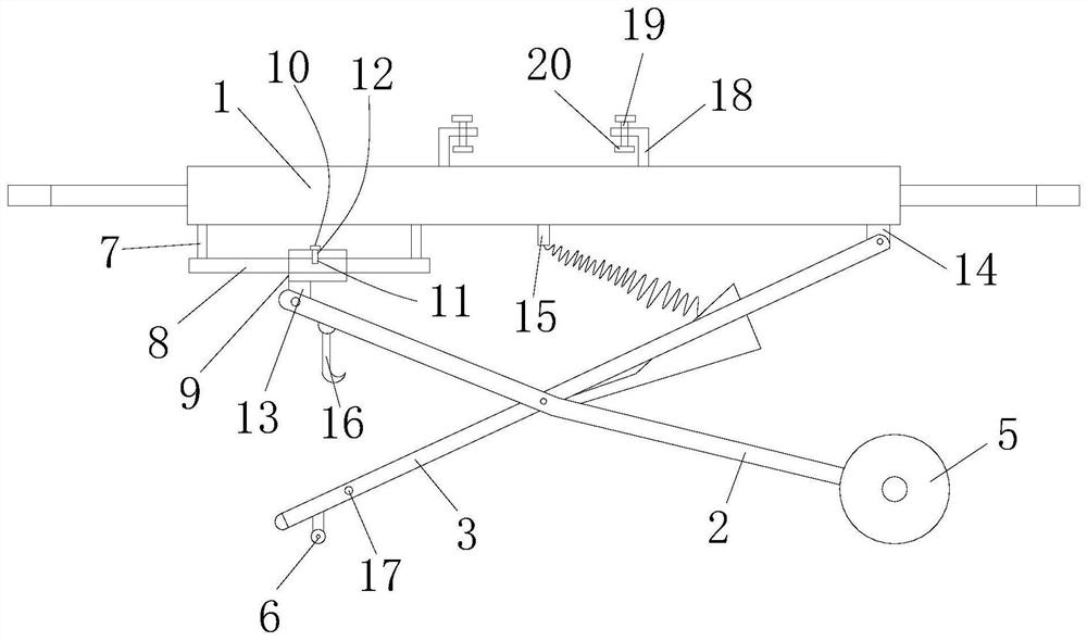
[0022] like figure 1 As shown, a liftable miter saw bracket includes a bracket main body 1, a locking component, a lifting assembly and an extension assembly; The upper end surface is provided with the locking part for locking the miter saw, and the lower end surface of the support body 1 is provided with the lifting assembly; wherein, the lifting assembly includes a first leg 2, a second leg 3, a moving part , the first pulley 5 and the second pulley 6; the upper end of the first leg 2 is set on one end of the bracket body 1 through the moving part, and the upper end of the second leg 3 is set on the bracket body 1, the first leg 2 and the second leg 3 are hingedly connected, the lower end of the first leg 2 is provided with the first pulley 5, and the second leg 3 The lower end is provided with the second pulley 6.
[0023] In this embodiment, the miter saw is installed on the bracket main body 1 through a locking part. When the height of the whole bracket needs to be adju...
Embodiment 2
[0025] like figure 1 As shown, the difference between this embodiment and the embodiment is that the moving part includes a connecting rod 7, a mounting rod 8, a slider 9 and a latch 10; the mounting rod 8 is arranged horizontally, and its two ends are connected through the The rod 7 is installed on the lower end of the bracket main body 1, the slider 9 is slidably arranged on the installation rod 8, and the installation rod 8 is provided with a plurality of the first jacks 11, the slider 9 is provided with a second insertion hole 12 , and the plug 10 can be inserted into the first insertion hole 11 and the second insertion hole 12 . The lower end surface of the slider 9 is equipped with a first mounting part 13, and the upper end of the first leg 2 is hinged to the first mounting part 13. The other end of the bracket main body 1 is installed with a second mounting part 14 , and the upper end of the second leg 3 is hinged to the second mounting part 14 . The lower end surfac...
Embodiment 3
[0029] like figure 1 As shown, the difference between the present embodiment and the second embodiment is that the locking part includes a right-angle block 18, a locking bolt 19 and a pressure block 20, and at least two of the right-angle blocks 18 are arranged in opposite positions on the On the upper end surface of the bracket body 1 , each of the right-angle blocks 18 is provided with the locking bolt 19 , and the lower end surface of the locking bolt 19 is provided with the pressing block 20 . When locking the miter saw on the support, tighten the locking bolt 19 to lock the briquetting block 20 on other parts of the miter saw.
PUM
 Abstract
Description
Claims
Application Information
 - R&D Engineer
- R&D Manager
- IP Professional
- Industry Leading Data Capabilities
- Powerful AI technology
- Patent DNA Extraction
Browse by: Latest US Patents, China's latest patents, Technical Efficacy Thesaurus, Application Domain, Technology Topic, Popular Technical Reports.
© 2024 PatSnap. All rights reserved.Legal|Privacy policy|Modern Slavery Act Transparency Statement|Sitemap|About US| Contact US: help@patsnap.com