
Patsnap Eureka
For R&D, Patsnap Eureka makes reading and utilizing patents & technical documents easy.
Patsnap Eureka AIR
Designed for self-driven R&D workflows. Generate viable solutions, solve complex R&D challenges, empower your innovation with AI.

Patsnap Eureka Materials
Designed for material experts only. Revolutionize your material R&D, from search, analyze, to developing new materials.

TechResearch
Generate reliable direction feasibility study reports for your R&D in just a few steps.

TechSeek
Discover and master advanced knowledge NOW. Basics, ideas, possibilities, all at once.

TechMind
As an expert in R&D Theories, TechMind can generates customized viable solutions instantly.

TechRisk
Analyze your overall solution with one click, know your potential R&D risks in advance.

TechMonitor
Get weekly tech updates, stay abreast of the latest tech innovations and key insights.
Embedded power lifting device
A lifting device and power device technology, which is applied in the direction of transportation and packaging, conveyor objects, object stacking, etc., can solve the problems of affecting the rhythm of taking tiles, affecting the efficiency of taking tiles, and difficulty in height adjustment.
- Summary
- Abstract
- Description
- Claims
- Application Information
AI Technical Summary
Problems solved by technology
Method used
Image

Examples
Embodiment 1
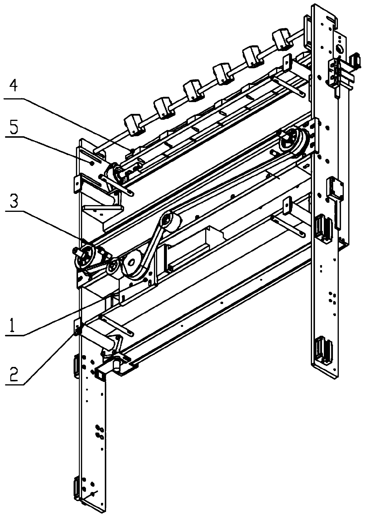
[0024] Embodiment 1: This built-in power lifting device mainly includes a power device 1, a guide device 2, a lifting device 3, an actuator 4 and a frame body 5, and the four guide devices 2 are respectively located on the four sides of the power device 1. Outside the apex, the power device 1 is provided with a lifting device 3, and the lifting device 3 is provided with an actuator 4. The above-mentioned power device 1, guide device 2, lifting device 3 and actuator 4 are all embedded in the frame body 5, wherein Under the guidance of the guide device 2, the power device 1 drives the lifting device 3 to lift and descend to ensure that the actuator 4 is in a proper working position. With built-in installation, the height can be adjusted freely, and various types of magnetic tiles can be stacked arbitrarily.
Embodiment 2
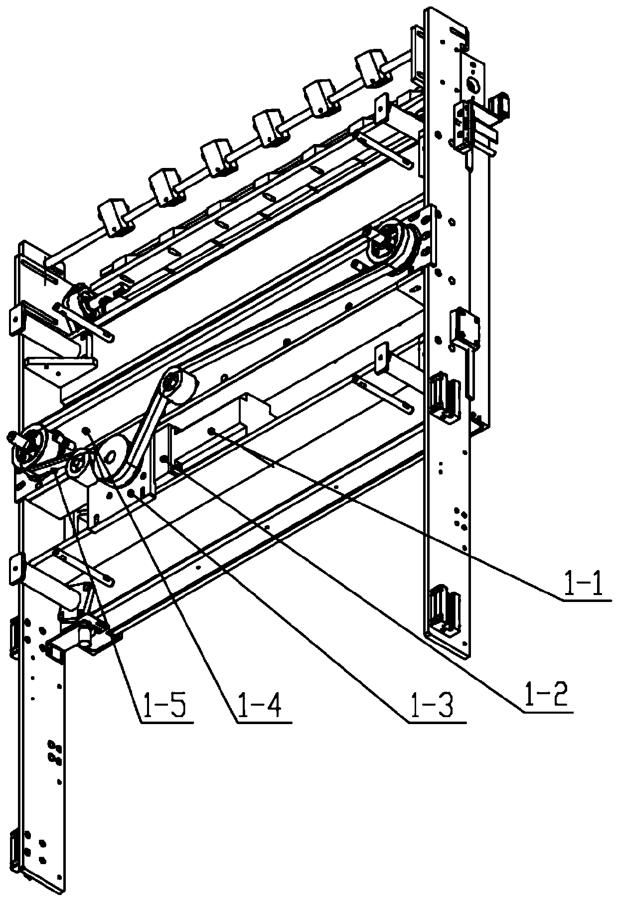
[0025] Embodiment 2: on the basis of embodiment 1, as figure 1 As shown, the power unit 1 includes a servo motor 1-1, a precision reducer 1-2, a power unit mounting plate 3, a synchronous pulley set 1-4 and a synchronous belt 1-5, and the drive of the servo motor 1-1 The end is connected to the precision reducer 1-2, and the precision reducer 1-2 is provided with a power device mounting plate 1-3, and the power device mounting plate 1-3 is provided with a synchronous belt pulley group 1-4, and the synchronous belt 1-5 is in turn Go through timing pulley set 1-4. Effectively provides sufficient power for telescopic boom action.
Embodiment 3
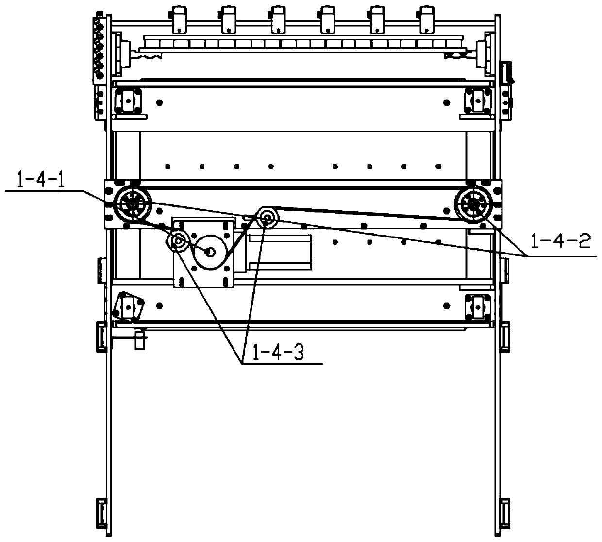
[0026] Embodiment 3: On the basis of Embodiment 2, the synchronous pulley set 1-4 includes a driving pulley 1-4-1, a driven pulley 1-4-2 and an idler pulley 1-4-3, and a precision reducer 1-2 is connected with the driving wheel 1-4-1, the left and right sides of the driving wheel 1-4-1 are provided with idler wheels 1-4-3 with high and low displacement, and the two ends of the frame body 5 are provided with driven wheels 1-4-2. Due to the adoption of the distribution of the synchronous pulley set, the force of the synchronous pulley set is more reasonable and satisfies the layout of the entire transmission system.
PUM
 Abstract
Description
Claims
Application Information
 - R&D Engineer
- R&D Manager
- IP Professional
- Industry Leading Data Capabilities
- Powerful AI technology
- Patent DNA Extraction
Browse by: Latest US Patents, China's latest patents, Technical Efficacy Thesaurus, Application Domain, Technology Topic, Popular Technical Reports.
© 2024 PatSnap. All rights reserved.Legal|Privacy policy|Modern Slavery Act Transparency Statement|Sitemap|About US| Contact US: help@patsnap.com